Introduction
Although 1-lead ECG (EKG) recorders are normally
used primarily for basic heart monitoring, checking for various arrhythmias, or simple
educational or research purposes, they can also be used for looking at the effects of
exercise on the ECG. One-lead recorders can also be used to accomplish full 12-lead
recordings in a sequential manner.
New, low-priced, 1-lead handheld ECG recorders
have become available for personal, home, and sports use, much as with home
blood-pressure/pulse recorders or glucose testers for diabetics. They also are suitable in
some emergency situations but only when used by medical or emergency personnel. Otherwise,
they can be used by the general public for personal recording of information, such as for
baseline information, routine monitoring, or during uncommon events, like with cardiac
event recorders. The recordings can then be shown to the person's cardiologist or
electrophysiologist or, for non-emergency or simple monitoring purposes, used by the
person himself or herself if he or she is able to interpret them. (ECGs are complex and
have a fairly steep learning curve. For a basic introduction, click here.)
One-lead ECG recorders may also be used for
monitoring the heart in association with regular exercise, workouts, and sports
activities. The actual recordings need to be done while the body is not moving, to avoid
artifacts from the muscles. However, "resting" measurements can nonetheless be
done during exercise and while the heart is responding to the exercise by briefly
interrupting the activity long enough to obtain a recording or immediately after finishing
the activity. Recordings can also be made while resting during the recovery period
following exercise. The use of any ECG recorder for exercise, however, is somewhat
akin to stress tests done in a clinic or hospital under medical supervision and should not
be done at home if cardiac problems are suspected or might occur or if clear emergency or
urgent situations exist (see disclaimer section below). Please consult a cardiologist if
in doubt.
The purpose of this article is to explain how to
use 1-lead (2 to 3 electrode contact) recorders in both exercise and 12-lead contexts.
When using the recorder for exercise purposes, one might want to focus on a particular
lead of the various 12 that are available, such as lead II or one of the chest leads
(V1-V6). Thus, I will explain how to obtain the different 12 leads first and then one can
choose which of them to use for measuring the ECG during exercise.
Important disclaimer: This
information is provided for educational, sports-associated (by healthy persons), research,
and non-emergency monitoring use only, not diagnostic or emergency uses by untrained
persons. In the event of an emergency or suspected-emergency situation, appropriate
medical help and facilities should be sought as quickly as possible. The only time that
personal ECG recorders should be even considered in urgent, emergency situations would be
if problems were to occur in remote locations to obtain useful information and/or while
waiting for transportation and help, that is, when the use of the recorders would not
delay possible help and might permit the collection of useful information for later use.
Source of 1-lead ECG recorders:
The descriptions and information in this web page are based on handheld recorders from Favoriteplus.com, a medical equipment division of
Favorite Imports LLC and a worldwide distributor of pulse oximeters, handheld ECG-EKG,
& fetal dopplers. They are "an international distributor and global provider of
medical devices for the hospital, emergency, home and specialist environments. Established
in 1998, ... grown to be one of the most reliable worldwide distributors of new and
innovative health products, medical devices and accessories." They have three models
of handheld ECG recorders currently available, the FP-RMH, FP-ICH, and FP180 (PC-80). For
further company information about the units and ordering, click here. For
general comparisons and a review that I conducted of the three units, click here.
I thank Favoriteplus for providing two of these recorders to me for purposes of
comparison.
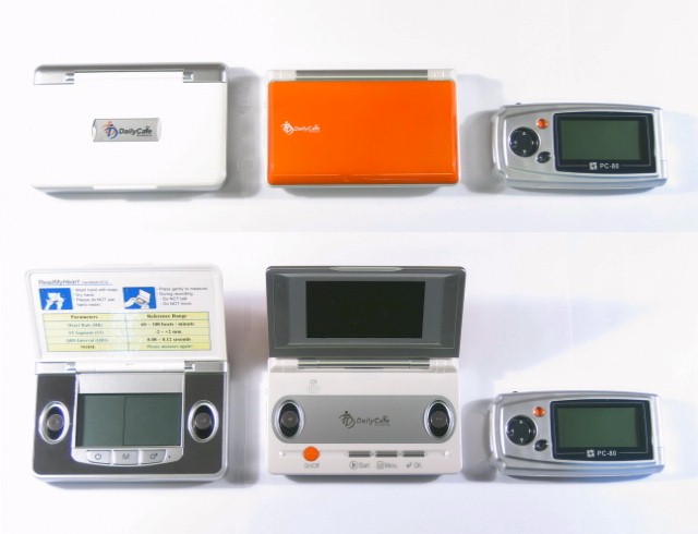
The following figure shows the three 1-lead
handheld recorders used for this article, from left to right: ReadMyHeart (FP-RMH,
hereafter referred to as RMH), InstantCheck (FP-ICH, referred as IC in the remainder of
the article) and PC-80 (FP180). Top row closed, bottom row open.
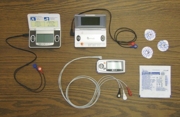
All three of these can be used with
thumb and hand electrode contacts with simple touch, without adhesive electrodes attached
to the skin. However, they also have cables with snap ends so adhesive electrodes can be
used if desired. The cables and adhesive electrodes are much less vulnerable to artifacts
and variability, provide much cleaner and more stable ECG recordings, and are highly
recommended. Compared to a normal 12-lead ECG system which uses 10 wires (four on the legs
and arms and six on the chest), the two or three electrodes used with these handheld units
are much simpler and not a hassle. The cables and adhesive snap electrodes were used in
all of the recordings done for this article.
The next figure shows an example of a standard 12-lead resting ECG
printout. If you are not already familiar with
resting 12-lead ECG recording and would like a basic introduction, click here. The example
in the figure was produced with a Nasiff 12-lead PC-based system. (For a link to the
Nasiff company, click here.) For additional 12-lead
comparisons in this article, as another example of a standard 12-lead system, I also used
a CardioPerfect recorder, the systems of which are currently available from Welch Allyn.

Procedures for obtaining 12-lead recordings with
1-lead recorders
To determine which wire should be designated as negative and which as
positive, the standard for negative is the right arm and the positive is the left arm. In
the case of RMH and IC, the red (RA) is negative and the blue (LA) is positive. For the
PC-80, the markings on the contact ends are confusing. After trial and error, I discovered
the white end ("RA") to be negative, as expected, but the black ("LA")
end is the ground and the red end ("LL") is the positive. In all cases, I
recommend using a marking pen to mark the -'s and +'s on the contact ends as appropriate
(except the black for the PC-80 which can be considered the ground).
All three recorders were used to obtain 12-lead recordings. The RMH unit,
with only two wires, is used to illustrate the procedures, below. The IC unit would be
connected as shown for the RMH. For the PC-80, which has three wires, the ground would be
attached to the right leg and the remaining neg and pos wires would be attached as with
the two wires of the other units.
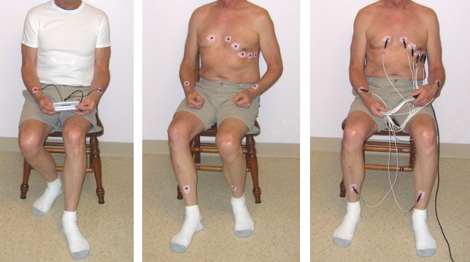
Photos below:
(Note: Resting ECGs are normally made on subjects in a horizontal,
reclined position, not sitting up. For demonstration and learning situations, however,
sitting quietly also usually works well. ECG results are virtually the same for many
people whether they are reclining or sitting, whereas they will be different for other
individuals.)
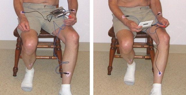
Left picture -- RMH being used with the electrodes as
recommended for the cable, with red on the right and blue on the left. This amounts to a standard
Lead I.
Middle picture -- Adhesive electrodes positioned on the
body for obtaining 12-lead recordings, with either a standard 12-lead system (as in the
right photo) or with 1-lead systems, as in the subsequent photos.
Right picture -- Running a standard 12-lead recording
using the Nasiff recorder, with all of the electrode contacts connected simultaneously.
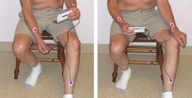
To obtain the remaining leads, the negative and positive recorder wires of
a 1-lead system can be sequentially moved to the different electrode positions on the
body, as demonstrated in the next series of photos.
Lead II (left photo) with the negative on the RA and the
positive on the LL.
Lead III (right photo) with the negative moved to the LA.
The augmented leads (aVR, aVL, and aVF) require an additional step. The
negative connection for the augmented leads is combined for two of the limb leads rather
than one. To accomplish that, a wire is needed to connect between two of the electrodes.
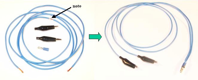
The connecting wire can be constructed simply by using a length of wire,
two alligator clips, and a small connector that the recorder's negative contact can snap
onto. Strip the insulation from both ends of the wire and at a short section half way
between the ends of the wire (see arrow in the photo below). Bend the wire where exposed
in the middle so it projects outward; push it into the connector; and solder in place.
(Alternatively, one could take two wires of equal length, expose both ends of each, and
twist an end of each together to form the middle section.) Then solder the alligator clips
onto the remaining ends. The finished connecting wire is shown on the right side of the
picture below.
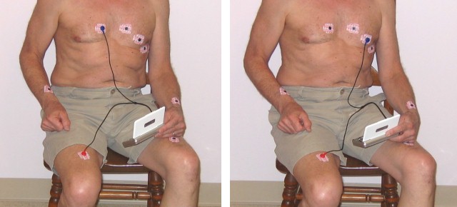
For Lead aVR (left photo below), the connecting wire is
clipped to the electrodes on the left arm and left leg, negative wire is attached to the
connector in the middle of the connecting wire (shown held in the left hand in the
picture), and the positive wire is attached to the electrode on the right arm. Lead
aVL (not pictured) is similar to aVR except that the arm connections are
switched, that is, the connecting wire for the negative end is moved to the right arm and
the positive end moved to the left arm.
Lead aVF (right photo) is obtained by attaching the
alligator clips and negative recorder wire to the two arm electrodes and the positive wire
to the LL.
Leads V1 through V6, the chest leads, use the negative
wire connected to the right leg and the positive placed at the appropriate chest
electrodes. Note: the limb leads can be placed essentially anywhere on the limb, as long
as they are at least 4 inches (10 cm) from the heart. Because the wires for the RMH (and
IC) are not long enough to reach between the lower leg (the traditional position for the
leg electrodes) and the chest, the right leg electrode was moved to the upper leg, as can
be seen in the photos below.
Examples: V1 connections are shown in left photo, V3 in the right photo.
(For the PC-80, which has three wires, leave the ground on the RL, the neg on the RA, and
move the pos to the various V positions.)
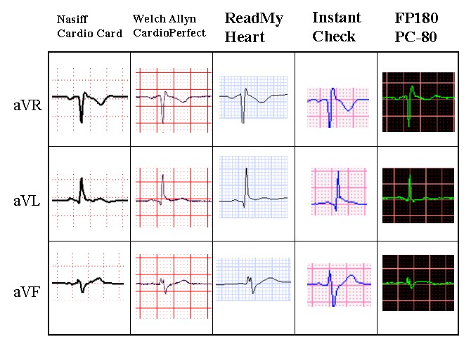
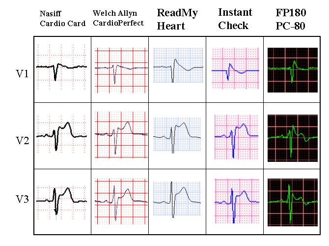
RESULTS: The outputs from each of the systems were
uploaded to a computer for analysis, display, and printing. The tracings for the following
figures were all taken from the computer screen monitor for each system. (The computer
screen backgrounds, grid, and line colors are different from their respective hardcopy
printouts.) The two standard 12-lead traces are shown in the two left columns, with the
three 1-lead handheld outcomes shown in the three right columns.
The resulting ECG traces are similar and consistent for all five systems,
except that the PC-80 seems to accentuate the QRS component and often shows the P and T
waves differently, particularly in amplitude, than in the standard 12-lead systems or the
other two 1-lead systems. For 12-lead purposes, the PC-80 works but not as well as the
other two 1-lead systems.


Printouts can be obtained from each of the systems, with
the full 12-lead systems producing the standard printout (see example at the start of this
article). The 1-lead systems obviously display and print only one lead at a time. To see
all 12 leads, you can either simply have a collection of all of the printouts, or else
cut/copy-paste a segment from each lead into one page. Below is an example of one that I
assembled for a set of RMH outputs.

For printing a clear copy on 8 1/2 x 11 inch paper of the above image via
PowerPoint or to use it as a template (see below), click
here.
I accomplished the above 12-lead page by setting up the table format,
adding labeling, then copying the screen views for each lead (by using Alt-Print Screen),
pasting into the PowerPoint slide, cropping the four sides down to the segment I wanted,
resizing so it would end up printed with each of the small boxes as 1 mm on a side, and
positioning it in its proper, standard place for 12-lead output. The most difficult part
was resizing each lead's image to get the small boxes to print out at 1 mm per side. Once
I had one that was the correct size (by trial and error), I used it as a template for
resizing the others by lining up their large box lines next to the templated one's large
box lines and resizing the new one until it matched. Then I moved the new ones into their
respective positions.
To create new 12-lead pages, you can download my PowerPoint version from
the link above and use it as a template. Copy-paste your outputs lead by lead, crop,
resize, etc., each as described above, and position them on top of the template outputs
for each lead. If you want to add different text, such as for the comments, simply use a
PowerPoint text box (with a white background) and place it over the template's respective
item.
Doing it with a computer is a bit tedious and time-consuming with all of
the copy-pasting, cropping, resizing, and organizing. Alternatively, one can just take the
printouts for all of the 12 leads and physically cut out segments with a scissors and
paste or tape them together on one sheet of paper, to be used as such or perhaps
photocopied to have it all flat on a single page.
Procedures for obtaining exercise
ECG recordings with 1-lead recorders
Using 1-lead ECG recorders for exercise ("stress") purposes is
relatively simple and straight forward. The only requirement is that when actually
recording, the subject must not be moving or else the body muscles will create a lot of
artifact and background noise. Thus, to record ECGs during the exercise, one must stop
briefly, long enough to make a recording, and then resume the activity. Similarly, at the
end of the activity one can record immediately following the activity. To do the recording
with a minimum of stopped time during exercise, keep the electrodes connected and be ready
to press the buttons to start the recording. In the case of the InstantCheck unit, you can
monitor the output for an extended period and it saves the last 30 seconds, so you can
have it running during actual exercise (and getting lots of artifact and noise) and then
simply stop and stand still for 30 seconds, at which point you can stop the recording and
it will save that 30 seconds.
Example:
I used the InstantCheck recorder set up for lead II and, at the same time,
put on a Holter ECG unit (which is used for extended ECG recording during activity). (The
Holter system subtracts out the muscle noise with complex computer functions and a
different placement of electrodes, using outputs that are referred to as
"channels" rather than "leads".) I recorded a period of rest prior to
exercise, exercised for 25 minutes (including 5 minute warm up and cool down periods) on a
stationary bicycle, then continued recording ECGs while subsequently resting.
For comparison, I also looked at the output from an earlier clinical
stress test, performed in a clinic/hospital setting with standard 12-lead stress-testing
equipment on a treadmill, with nurse technicians running the equipment, monitors, and
recording, plus a cardiologist supervising.
Here is a sample of the printed output from the clinic results for two of
the 12 leads while at a comparable heart rate (133-136 BPM) followed by samples of the
printouts for the Holter and 1-lead recorders. For all practical purposes, the outcomes
are all the same, demonstrating that 1-lead systems can be used to produce good
exercise/stress-test results.

Finally, here is a sample from the full sequence for the 1-lead system,
from resting prior to the workout, a sample taken in the middle of the exercise (by
stopping briefly to obtain the recording), and two samples during the recovery period.

Comments and Conclusions
Single-lead ECG systems not only work, but they work remarkably well for
conducting both 12-lead and exercise ECGs. It must be noted, however, that the 12-lead
results from 1-lead systems are sequential, not simultaneous as are the ones recorded with
most standard 12-lead systems. Similarly, exercise recordings cannot be done continuously
during the actual activity as with Holter units or standard stress-testing equipment.
Instead, quick recordings must be made during brief interruptions of the activity, while
the heart is still responding to the activity.
Of the three 1-lead handheld systems discussed in this article, the PC-80
produced the least satisfactory 12-lead outcomes. It does, however, detect beats against
other muscle noise better than the other two during actual activity. Trying to make
recordings during active movement, nonetheless, is noisy and messy with these simple
systems regardless of which of the three is used. The PC-80 appears most suitable for its
intended purpose of being able to quickly record arrhythmias (see the comparative
review of these three 1-lead recorders).
If one is really serious (and has the equipment, or finances to obtain
full, standard 12-lead or Holter equipment), the standard equipment still produces better
results and the kinds of outputs that cardiologists and electrophysiologists are more
accustomed to reading. Nonetheless, particularly for persons on a limited budget, wanting
a simple home personal system, or wanting something very portable and handy, including for
traveling, the small, handheld, 1-lead systems will do the job.
To contact the author, e-mail: james.grier@ndsu.edu
Author's web page: James W. Grier
Department
of Biological Sciences, NDSU
![[NDSU home page]](http://www.ndsu.edu/ndsu/gif/backbuttons/ndsu.back.gif)
![[Site Search]](http://www.ndsu.edu/ndsu/gif/backbuttons/search.back.gif)
Last updated: 9/05/2008