Conducting Polymer Nanospheres
A relatively simple method for the synthesis of unagglomerated polypyrrole nanospheres of a controlled size, Dispersion Assisted Polymerization of Stable Nanospheres via Ozone-oxidation (DAPSNO), has been developed in the Gelling laboratory. The resulting nanospheres display high size uniformity as well as a nicely spherical morphology as determined via transmission electron microscopy (TEM), scanning electron microscopy (SEM), and NICOMP particle sizer.
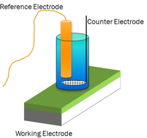


Electrochemical Impedance Spectroscopy (EIS)
EIS is useful as it provides one with more information than a DC resistance measurement of the same system as it provides frequency dependant information which is important in coating degradation. A schematic of an electrochemical cell often used on the right.
In short, EIS is an AC method where a small voltage perturbation is made to a sample, usually about its naturally occurring open circuit potential. The corresponding current flow due to the voltage perturbation is measured. A form of ohms law is followed letting one calculate the impedance (ohms) as the voltage and current are known: Z(ω)=V(ω)/I(ω), where Z(ω) is the complex impedance and accounts for the relationship between amplitudes of the voltage and current signals as well as the phase shift between them. V(ω) and I(ω) are the voltage perturbation and corresponding current, respectively. Circuit modeling can be performed on the resulting EIS data using commercially available software.
For a standard coating, the behavior typically observed is that of a Randles Cell is shown on the right. Changes are observed with respect to immersion time or exposure to accelerated weathering as seen at the right in the Bode and Nyquist graphs.
Scanning Vibrating Electrode Technique (SVET)
Current density above a substrate immersed in an electrolyte solution can be mapped using the scanning vibrating electrode technique (SVET). The technique uses an electrode vibrating in an electrolyte above the surface of a sample to detect potential gradients in the electrolyte. The experimental setup is shown at the right.
Typical results for a coating are presented at the right, where the cathodic and anodic currents are primarily confined to the artificial defect that was created prior to immersion in dilute Harrison’s solution.
Field Coating Measurement
An important aspect of the maintenance schedule of any structure that is exposed to the environment is the detection of corrosion, which could potentially lead to failure. The most common way to protect against corrosion is to apply protective coatings to the substrate. Determining coating integrity and the corrosion protection the coatings provide to the substrate is a relatively simple procedure in the lab. However field-testing coatings for corrosion protection is relatively more difficult. Although the traditional EIS testing method is a very reliable and trusted technique for laboratory testing of coatings there are some limitations when this technique is used for field testing of coatings. These limitations include a required electrical connection to the substrate which results in local coating destruction.
In order for EIS measurements to become a reliable technique for corrosion field testing a two electrode testing technique was developed. Instead of the substrate material acting as the working electrode, in dual cell testing the working electrode is a platinum plated electrode. In this setup the current is measured at the combined reference/counter electrode which is another platinum plated electrode. Again, from the known voltage and the measured current the impedance of the coating is calculated. The technique has been successfully used to determine the impedance of coatings without any damage to the coating or substrate as shown at the right.
__
This Web page represents the views of the author and not necessarily those of North Dakota State University.
NDSU is not responsible or liable for its contents.