Title

Spray Equipment and Calibration

(AE73, Revised October 2025)
Lead Author
Lead Author:
Revised by Rob Proulx Agriculture Technology Systems Specialist
Availability
Availability:
Web only
Publication Sections

Many pesticides used to control weeds, insects and disease in field crops, ornamentals, turf, fruits, vegetables and rights-of-way are applied with hydraulic sprayers. Tractor-mounted, pull-type, pickup-mounted and self-propelled sprayers are available from numerous manufacturers to do all types of spraying. Spray pressures range from near 0 to over 300 pounds per square inch (PSI), and application rates can vary from less than 1 to over 100 gallons per acre (GPA). All sprayers have several basic components: pump, tank, agitation system, flow-control assembly, pressure gauge and distribution system (Figure 1).

Properly applied pesticides should be expected to return a profit. Improper or inaccurate applications are usually very expensive and will result in wasted chemical, marginal pest control, excessive carryover or crop damage.

Agriculture is consistently under intense economic and environmental pressure. The high cost of pesticides and the need to protect the environment are incentives for applicators to do their very best in handling and applying pesticides.

Studies have shown considerable application errors due to improper calibration of the sprayer. A North Dakota study found that 60% of the applicators were over- or under-applying pesticides by more than 10% of their intended rate. Several were in error by 30% or more. A study in another state found that four out of five sprayers had calibration errors and one out of three had mixing errors.

Pesticide applicators need to know proper application methods, chemical effects on equipment, equipment calibration and correct cleaning methods. Equipment should be recalibrated periodically to compensate for wear in pumps, nozzles and metering systems. Dry flowable formulations may wear nozzle tips and cause an increase in application rates after spraying as little as 50 acres.

Improperly used agricultural pesticides are dangerous. It is extremely important to observe safety precautions, wear protective clothing when working with pesticides and follow directions for each specific chemical. Consult the operator’s manual for detailed information on a particular sprayer.

Pump and Flow Controls

Asprayer is often used to apply different materials, such as pre-emergent and postemergence herbicides, insecticides and fungicides. A change of nozzles may be required, which can affect spray volume and system pressure. The type and size of pump required is determined by the pesticide used, recommended pressure and nozzle delivery rate. A pump must have sufficient capacity to operate a hydraulic agitation system, as well as supply the necessary volume to the nozzles. A pump should have a capacity at least 25% greater than the largest volume required by the nozzles. This will allow for agitation and loss of capacity due to pump wear.

Pumps should be resistant to corrosion from pesticides. The materials used in pump housings and seals should be resistant to chemicals, including organic solvents. Other things to consider are initial pump cost, pressure and volume requirements, ease of priming and available power source.

Pumps used on agricultural sprayers are normally of four general types:

  • Centrifugal pumps
  • Roller or rotary pumps
  • Piston pumps
  • Diaphragm pumps

Centrifugal Pumps and Controls

Centrifugal pumps are commonly used for self-propelled sprayers and large trailed sprayers. They are durable, simply constructed and can readily handle abrasive materials. Because of the high capacity of centrifugal pumps, hydraulic agitators can and should be used to agitate spray solutions even in large tanks.

Centrifugal pumps feature a distinctive “steep performance curve” where discharge volumes decrease rapidly at the upper limits of the pump’s operating pressure range. This is an advantage as it permits controlling pump output without a relief valve. However, since centrifugal pump performance is sensitive to speed (Figure 2), inlet pressure variations may produce uneven pump output under some operating conditions.

Centrifugal pumps should operate at speeds of about 3,000 to 4,500 revolutions per minute (RPM). When driven with the tractor PTO, a speed-up mechanism is necessary. A simple and inexpensive method of increasing speed is with a belt and pulley assembly. A planetary gear system is another option. The gears are completely enclosed and mounted directly on the PTO shaft. Centrifugal pumps can also be driven by a direct-connected hydraulic motor (as in Figure 2, for example) and flow control operating off the tractor hydraulic system. This allows the PTO to be used for other purposes, and a hydraulic motor may maintain a more uniform pump speed and output with small variations in engine speed. Pumps may also be driven by a direct-coupled gasoline engine, which will maintain a constant pressure and pump output independent of vehicle engine speed.

Centrifugal pumps should be located below the supply tank to aid in priming and maintaining a prime. Also, no pressure relief valve is needed with centrifugal pumps. The proper way to connect components on a sprayer using a centrifugal pump is shown in Figure 3. A strainer located in the discharge line protects nozzles from plugging and avoids restricting the pump input. Two control valves are used in the pump discharge line, one in the agitation line and the other to the spray boom. This permits controlling agitation flow independent of nozzle flow. The flow from centrifugal pumps can be completely shut off without damage to the pump. Spray pressure can be controlled by a throttling valve, eliminating the pressure relief valve with a separate bypass line. A separate throttling valve is usually used to control agitation flow and spray pressure. Electrically controlled throttling valves are popular for remote pressure control and are installed in an optional bypass line as shown in Figure 3.

A boom shut-off valve allows the sprayer boom to be shut off while the pump and agitation system continue to operate. Electric solenoid valves eliminate the need for chemical-carrying hoses to be run through the cab of the vehicle. A switch box that controls the electric valve is mounted in the vehicle cab. This provides a safe operator area if a hose should break.

To adjust for spraying with a centrifugal pump (Figure 3), open the boom shut-off valve, start the sprayer and open the throttling control valve until pressure comes up to 10 PSI over the desired spraying pressure. Then adjust the agitation control valve until good agitation is observed in the tank. If the boom pressure has dropped slightly because of the agitation, readjust the main control valve to bring the pressure up to 10 PSI above spraying pressure. Then open the bypass valve to bring the boom pressure down to the desired spray pressure. This valve can be opened or closed as needed to compensate for system pressure changes so a constant boom pressure can be maintained. Be sure to check for uniform flow from all nozzles.

Roller Pumps and Controls

Roller pumps are commonly used with three-point sprayers. They consist of a rotor with resilient rollers that rotate within an eccentric housing. Roller pumps are popular because of their low initial cost, compact size and efficient operation at tractor PTO speeds. They are positive displacement pumps and self-priming. Larger pumps are capable of moving 50 GPM and can develop pressures up to 300 PSI. Roller pumps tend to show excessive wear when pumping abrasive materials, which is a limitation with this pump.

Material options for roller pumps include cast iron and corrosion-resistant silver alloy or Ni-resist housings; PTFE-coated, polypropylene or Teflon rollers; and Viton or Buna-N rubber seals. Corrosion-resistant housings are recommended for pesticides, especially glyphosate or other acidics. Poly rollers are used for all-around spraying; they are suitable for fertilizers and weed and insect control chemicals, including suspensions. PTFE-coated rollers provide additional corrosion resistance. Viton seals are suitable for all purposes; Buta-N seals can be used if pumping applications are limited to fertilizers, plain water or abrasive powders in suspension. Roller pumps should have factory-lubricated sealed ball bearings, stainless steel shafts and replaceable shaft seals.

The recommended hookup for roller pumps is shown in Figure 4. A control valve is placed in the agitation line so the bypass flow is controlled to regulate spraying pressure. Systems using roller pumps contain a pressure relief valve (Figure 5). These valves have a spring-loaded ball, disc or diaphragm that opens with increasing pressure so excess flow is bypassed back to the tank, preventing damage to sprayer components when the boom is shut off.

The agitation control valve must be closed, and the boom shut-off valve must be opened to adjust the system (Figure 4). Start the sprayer, making sure flow is uniform from all spray nozzles, and adjust the pressure relief valve until the pressure gauge reads about 10 to 15 PSI above the desired spraying pressure. Slowly open the throttling control valve until the spraying pressure is reduced to the desired point. Replace the agitator nozzle with one having a larger orifice if the pressure will not come down to the desired point.

Use a smaller agitation nozzle if insufficient agitation results when spraying pressure is correct and the pressure relief valve is closed. This will increase agitation and permit a wider open control valve for the same pressure.

Piston Pumps and Controls

Piston pumps are positive displacement pumps, where output is proportional to speed and independent of pressure. Piston pumps work well for wettable powders and other abrasive liquids. They are available with either rubber or leather piston cups, which permit the pump

to be used for water or petroleum-based liquids and a wide range of chemicals. Lubrication of the pump is usually not a problem due to the use of sealed bearings.

The use of piston pumps for farm crop spraying is limited partly by their relatively high cost. Piston pumps have a long life, which makes them economical for continuous use. Larger piston pumps have a capacity of 25 to 35 GPM and are used at pressures up to 600 PSI. This high pressure is useful for high-pressure cleaning, livestock spraying or crop insect and fungicide spraying. A piston pump requires a surge tank at the pump outlet to reduce the characteristic line pulsation.

The connection diagram for a piston pump is shown in Figure 6. It is similar to a roller pump, except that a surge tank has been installed at the pump outlet. A damper is used in the pressure gauge stem to reduce the effect of pulsation. The pressure relief valve should be replaced by an unloader valve (Figure 7) when pressures above 200 PSI are used. This reduces the pressure from the pump when the boom is shut off, so less power is required. If an agitator is used in the system, agitation flow may be influenced when the valve is unloading.

Open the throttling control valve and close the boom valve to adjust for spraying (Figure 6). Then adjust the relief valve to open at a pressure 10 to 15 PSI above spraying pressure. Open the boom control valve and make sure flow is uniform from all nozzles. Then adjust the throttling control valve until the gauge indicates the desired spraying pressure.

Diaphragm Pumps and Controls

Diaphragm pumps are commonly used with ATV sprayers and nutrient application systems. They can handle abrasive and corrosive chemicals at high pressures and permit a wide selection of flow rates.

Large diaphragm pumps can produce high pressures (to 850 PSI) along with high volume (60 GPM), but the price of diaphragm pumps is relatively high. Therefore, diaphragm pumps are best suited for applications where their attributes are required, such as when spraying highly abrasive or corrosive chemicals or when both high pressure and volume are required.

The spray system hookup for diaphragm pumps is the same as for piston pumps (Figure 6). Be sure the controls and all hoses are large enough to handle the high flow and that all hoses, nozzles and fittings are capable of handling high pressure.

Spray System Pressure

The type of pesticide and nozzle being used usually determines the pressure needed for spraying. This pressure is usually listed on the pesticide label. Low pressures of 15 to 40 PSI may be sufficient for spraying most herbicides or fertilizer, but high pressures up to 400 PSI or more may be needed for spraying insecticides or fungicides.

Spray nozzles are designed to be operated within a certain pressure range. Higher than recommended pressures increase the delivery rate and reduce the droplet size, and they may distort the spray pattern. This can result in excess spray drift and uneven coverage. Low pressures reduce the spray delivery rate, and the spray material may not form a full-width spray pattern unless the nozzles are designed to operate at lower pressures.

Always follow the pressure recommendations of nozzle manufacturers as explained in product catalogs.

Avoid using nozzles too small for the job. To double the spray rate from nozzles, the pressure must be increased by a factor of four. This may exert excessive strain on sprayer components, increase wear on the nozzles and produce drift-susceptible droplets.

A pressure gauge should have a total range twice the maximum expected reading. The gauge should indicate spray pressure accurately. Measuring the discharge rate at a specific pressure on the gauge is recommended during calibration. Install a gauge protector or damper to prevent damage.

Sprayer Tanks

The tank should be made of a corrosion-resistant material. Suitable materials most commonly used to manufacture sprayer tanks are stainless steel and polyethylene plastic. Pesticides may be corrosive to certain materials. Care should be taken to avoid using incompatible materials. Aluminum, galvanized or steel tanks must not be used. Some chemicals react with these materials, which may result in reduced effectiveness of the pesticide or rust or corrosion inside the tank.

Keep tanks clean and free of rust, scale, dirt and other contaminants that can damage the pump and nozzles. Also, contamination may collect in the nozzle and restrict chemical flow, resulting in improper spray patterns and application rates. Debris can clog strainers and restrict flow of spray through the system.

Flush the tank with clean water after spraying is completed. A tank with a drain hole at the bottom near one end helps allow complete rainage. A tank with a small sump in the bottom is another excellent alternative. An opening in the top large enough for internal inspection, cleaning, and service is a necessity. For further details on sprayer cleanout, refer to Purdue Extension publication PPP-108: Removing Herbicide Residues from Agricultural Application Equipment.

Tank capacity must be known to add the correct amount of pesticide. Most new tanks have capacity marks on the side or a sight gauge to indicate the fluid level. The sight gauge should have a shut-off valve at the bottom to allow closing in case of damage. Your sprayer should be sitting on level ground when reading the gallons remaining in the tank. Incorrect volume readings cause improper amounts of pesticide to be added, which can result in crop injury, poor pest control or increased cost.

Tank Agitators

An agitator in the tank is needed to mix the spray material uniformly and keep chemicals in suspension (Figures 8 and 9).

The need for agitation depends on pesticide type. Liquid concentrations, soluble powders and emulsifiable liquids require little agitation. Intense agitation is required to keep wettable powders in suspension, so a separate agitator, either a hydraulic or mechanical type, is required. Adjustable agitators are desirable to minimize the foaming that can occur with vigorous agitation of certain pesticides as the volume in the tank decreases. Agitation should be started with the tank partly filled and before pesticides are added to the tank. With wettable powders and flowables, continue to agitate while filling the tank and during travel to the field. Don’t allow pesticides to settle, as the spray mix must be kept uniform to avoid concentration error. This is especially important with wettable powders because they don’t dissolve, are usually much heavier than water and are extremely difficult to return to suspension after they have settled out in the tank and hoses.

A sparge tube is commonly used with modern high-capacity sprayers, while hydraulic jet or mechanical agitators are appropriate for smaller sprayer tanks (e.g., 350 gallons or smaller).

The hydraulic jet agitator is operated by a pressure line hooked into the spray system directly behind the pump. The hydraulic jet agitator should be positioned to provide agitation throughout the tank. A flow of 5 to 6 GPM for every 100 gallons of tank capacity is usually adequate for an orifice jet agitator. Several types of venturi-suction agitators are available that help stir the liquid with less flow. With these, the agitation flow from the pump can be reduced to 2 or 3 GPM per 100-gallon tank capacity. Do not install a jet agitator on the pressure regulator bypass line, as low pressure and intermittent liquid flow will usually produce poor results. Agitation would occur only when the spray boom is shut off.

A mechanical agitator with a shaft and paddles will do an excellent job of maintaining a uniform mixture but is usually more costly than a jet agitator. Mechanical agitators must be operated by a separate drive, hydraulic motor or 12-volt electric motor. They should be run between 100 and 200 RPM. Higher speeds may cause foaming of the spray solution

Strainers

Aplugged nozzle is one of the most frustrating problems that applicators experience with sprayers. Properly selected and positioned strainers and screens will do much to prevent nozzle plugging and reduce nozzle wear.

Three types of strainers are commonly used on agricultural sprayers: tank-filler strainers, line strainers and nozzle screens. Strainer numbers (e.g., 20-mesh, 50-mesh or 100-mesh) indicate the number of openings per inch. Strainers with high numbers have smaller openings than strainers with low numbers.

Coarse basket strainers set in the tank-filler opening prevent debris from entering the tank as it is being filled. A 16- or 20-mesh tank-filler strainer will also restrain lumps of wettable powder until they are broken up, helping to give uniform mixing in the tank.

The line strainer is the most critical strainer of the sprayer (Figure 10). It usually has a screen size of 16 to 80 mesh, and it can be positioned between the tank and the pump, between the pump and the pressure regulator or close to the boom, depending upon the type of pump used. Roller and other positive displacement pumps should have a line strainer (40- or 50-mesh) located on the inlet line of the pump to remove material that would damage the pump. In contrast, the inlet of a centrifugal pump must not be restricted. Instead, a line strainer (usually 50-mesh) should be located on the outlet side of a centrifugal pump to protect the spray and agitation nozzles. Be sure to clean the line strainer regularly.

Self-cleaning line strainers are available for sprayers (Figure 11). However, these units require additional pump flow capacity to continually flush a portion of the fluid over the screen and carry trapped material back to the spray tank.

Nozzles are the third location where screens are located (Figure 12). Small-capacity nozzles must have screens to prevent plugging. Typically, 24-, 50- or 100-mesh screens are used, depending on nozzle design and capacity. Larger capacity nozzles typically use coarser screens, as there is little benefit in using a screen size smaller than the nozzle orifice itself. If nozzle flow rate exceeds 1 GPM, a nozzle screen or strainer is not usually necessary if a good line strainer is used.

Follow nozzle manufacturer recommendations for strainer mesh sizing as well as any applicable pesticide label instructions. For example, product labels for herbicides containing atrazine or mesotrione, two relatively thick active ingredients, commonly list a requirement for 50-mesh or coarser nozzle screens. Slotted strainers, rather than screens, are sometimes used with liquids containing suspended solids.

Sprayer Distribution System

The sprayer will not function properly without proper hoses and controls to connect the tank, pump and nozzles, which are the key components of the spraying system.

Select hoses and fittings to handle the chemicals at the selected operating pressures and quantities. Peak pressures, greater than average operating pressures, are often encountered. These peak pressures usually occur as the spray boom is shut off. Choose components on the basis of composition, construction and size.

Hose must be flexible, durable and resistant to sunlight, oil, chemicals and general abuse such as twisting and vibration. Two widely used materials that are chemically resistant are ethylene vinyl acetate (EVA) and ethylene propylene dione monomer (EPDM).

Suction hoses should be air-tight, non- collapsible, as short as possible and as large as the pump intake. A collapsed suction hose can restrict flow and “starve” a pump, causing decreased flow and damage to the pump. If you cannot maintain spray pressure, check the suction line to be sure that it is not restricting flow.

Other lines, especially those between the pressure gauge and the nozzles, should be as straight as possible, with a minimum of restrictions and fittings. The proper size of these varies with the size and capacity of the sprayer. A high but not excessive fluid velocity should be maintained throughout the system. Lines that are too large reduce the fluid velocity so much that some pesticides, such as dry flowables or wettable powders, may settle out, clog the system and reduce the amount of pesticide being applied. If the lines are too small, an excessive pressure drop will occur. A flow velocity of 5 to 6 feet per second is recommended. Suggested hose sizes for various pump flow rates are listed in Table 1. Some chemicals will react with plastic materials. Check sprayer and chemical manufacturers’ literature for compatibility.

Boom stability is important in achieving uniform spray application. The boom should be relatively rigid in all directions. Swinging back and forth or up and down is not desirable. Certain sprayers feature gauge wheels mounted near the end of the boom to maintain uniform boom heights, especially on hilly or uneven terrain. The boom height should be adjustable from 1 to 4 feet above the target.

Table 1. Guide for determining hose size.

Pump Output
(gals/min.)
Suction HoseDischarge Hose
(inside diameter in inches)
Under 12 GPM3/45/8
12­–25 GPM13/4
25–50 GPM1-1/41
50–100 GPM1-1/21-1/4

Nozzles

Functions

The nozzle is a critical part of any sprayer. Nozzles perform three functions:

  1. Regulate flow
  2. Atomize the mixture into droplets
  3. Disperse the spray in a desirable pattern.

There is no single perfect nozzle. There are a variety of nozzle designs, and each is best suited for certain purposes and less desirable for others. The chart in Table 2 compares various nozzles, their droplet sizes and their effectiveness for broadcast spraying. Table 3 compares nozzle characteristics for banding or directed spraying.

Nozzles determine the rate of pesticide distribution at a particular pressure, forward speed and nozzle spacing. Drift can be minimized by selecting nozzles that produce the largest droplet size while providing adequate coverage at the intended application rate and pressure.

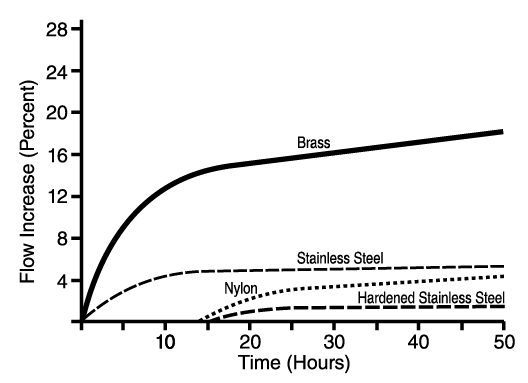
Nozzles are made from several types of materials. The most common are brass, plastic, nylon, stainless steel, hardened stainless steel and ceramic. Brass nozzles are the least expensive but are soft and wear rapidly. Nylon nozzles resist corrosion, but some chemicals cause thermoplastic to swell. Nozzles made from harder metals usually cost more but are usually more durable. The durability of various nozzle materials compared to brass is shown in Figure 13. Nozzles wear with use and flow rate. It is important to check and replace worn nozzles regularly, because worn nozzles may increase pesticide application cost and cause crop injury, illegal rates or residue. For example, a 10% increase in flow rate may not be readily noticeable; however, spraying 160 acres with a pesticide that costs $35 per acre at the increased rate would cost an extra $3.50 per acre or $560 more for the field.

Figure 13
Photo Credit:
NDSU Photo
Wear rates of various nozzle materials.

Each nozzle on a sprayer should apply the same amount of pesticide. Streaking may occur if one nozzle applies more or less than adjacent nozzles. Nozzle flow rates must be monitored by regularly collecting the flow from each nozzle under operating conditions and comparing the outputs. If the discharge from a nozzle varies more than 10% above or below the average of all the nozzles, replace it.

Do not mix nozzles of different materials, types, discharge angles or gallon capacity on the same sprayer. Any mixing of nozzles will produce uneven spray patterns.

Care must be used when cleaning clogged spray nozzles. The nozzle should be removed from the nozzle body and cleaned with a soft-bristled nozzle cleaning brush. Blowing the dirt out with compressed air is also an excellent method. Do not use a small wire or jackknife tip to clean the nozzle orifice, as it is easily damaged. An interdental toothbrush is inexpensive, highly effective and will not damage the nozzle orifice.

Table 2. Nozzle guide for broadcast spraying.

Table 3. Nozzle guide for band and directed spraying.

Flow Rate

Nozzle flow rate is a function of the orifice size and pressure. Manufacturers’ catalogues list nozzle flow rates at various pressures and discharge rates per acre at various ground speeds. In general, as pressure goes up flow rate increases, but not in a one-to-one ratio. To double the flow rate, you must increase the pressure four times. Many spray control systems use this principle to control output. They increase pressure to maintain correct application rates with an increase in speed. Use caution in speed changes as the spray system pressures may need to operate above recommended nozzle operating ranges, producing excessive driftable fines.

Drop Size

Once the spray material leaves the nozzle orifice, only droplet size, droplet number and the velocity of drops can be measured. Droplet size is measured in microns. A micron is one millionth of a meter; 1 inch contains 25,400 microns. To give this measure some perspective, a human hair is approximately 56 microns in diameter.

All hydraulic nozzles produce a range of droplet sizes – some large droplets to many small droplets. The volume median diameter VMD) is a summary statistic used to characterize the range of droplet sizes produced by a nozzle. The VMD is the droplet size where 50% of the nozzle’s volume is composed of droplets smaller than the VMD and 50% of the volume is in larger droplets. The VMD should not be confused with the NMD (number median diameter), which is usually a smaller number. The NMD is the median size that divides the spectrum of droplets into an equal number of smaller and larger drops.

Nozzle design affects the droplet size, and droplet size is a primary consideration when choosing an appropriate nozzle for a pesticide application. Large droplets are less prone to drift, but small droplets may be more desirable for better coverage. Pressure also affects droplet size – higher pressures produce smaller droplets.

The size of the spray droplet has a direct influence on the efficacy of the applied chemical, so selecting the proper nozzle type to control spray droplet size is an important management decision. When the average droplet diameter is reduced to half its original size, eight times as many droplets can be produced from the same flow. A nozzle that produces small droplets can theoretically cover a greater area with a given flow. However, extremely small drops may not deposit on the target, as evaporation is reducing their size during travel to the target and air currents in the drop pathway may interrupt the drop movement and carry the drop off-target. Environmental conditions of wind and humidity, which is best expressed as Delta T, can have a major effect on drop deposit on the target when small drops are used to apply pesticides.

Water-sensitive paper can be used to assess droplet size and density. Experience has shown that for low volume sprays with medium-sized droplets, insecticides should have a density of not less than 20 to 30 droplets/cm2, herbicides 20 to 40 droplets/cm2 and fungicides 50 to 70 droplets/cm2. Drop number and size can be estimated with a hand lens or the SnapCard mobile app.

Nozzle Check Valves

Nozzle bodies are typically equipped with check valves that produce a quick shutoff and prevent dripping at the nozzle during turns or transport. Diaphragm check valves (Figure 14) are best at stopping nozzle drip. Ball check valves are more susceptible to corrosion than diaphragm check valves and are not as trouble-free. Check valves cause a pressure drop of 5 to 10 PSI, depending on the spring pressure in the valve. Check valves allow the nozzles to be changed without material leaking from the boom.

Nozzle Spray Patterns

Every spray pattern has two basic characteristics: the spray angle and the shape of the pattern.

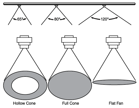
Most agricultural nozzles have an angle from 65 to 120 degrees. Narrow angles produce a more penetrating spray; wide-angle nozzles can be mounted closer to the target, spaced farther apart on the boom, or provide overlapping coverage (Figure 15).

Though there are a multitude of spray nozzles, there are only three basic spray patterns: the flat fan, the hollow cone and the full cone. Each of these has specific characteristics and applications.

Figure 15
Photo Credit:
NDSU Photo
Basic nozzle spray angles and patterns.

Flat-Fan Spray Nozzles

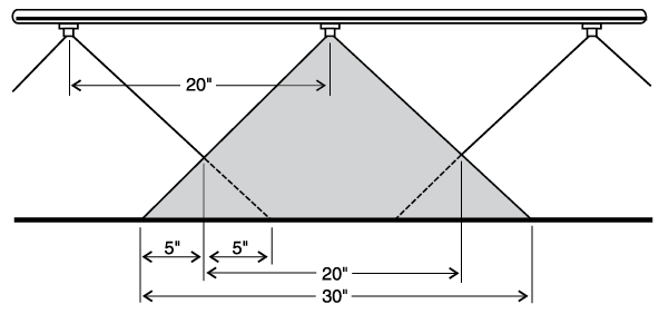
Flat-fan nozzles are widely used for broadcast spraying of herbicides and some insecticides. They produce a tapered-edge flat-fan spray pattern. Less material is applied along the edges of the spray pattern, so the patterns of adjoining nozzles must be overlapped to give uniform coverage over the length of the boom. For maximum uniformity, overlap should be about 30% to 50% of the nozzle spacing at the target level (Figure 16). Normal operating pressure is defined by nozzle specifications.

Lower pressures produce larger droplets, which reduces drift potential, while higher pressures produce small drops for maximum plant coverage, but small drops are more susceptible to drift. Extended range flat fan nozzles will operate over a range of 15 to 60 PSI without causing a significant effect on the width of the spray pattern. Lower operating pressure produces larger droplets and reduces the drift potential, while the higher pressures produce fine drops with higher drift potential. Extended range nozzles work well with automatic spray controllers, but realize that droplet size will change as the controller adjusts system pressure.

Flat-fan nozzles are available in several spray discharge angles. The most commonly used configurations are listed in Table 4. Proper spray boom height depends on nozzle discharge angle and is measured from the target to the nozzle. For postemergence pesticides, the target is the growing crop and not the soil surface (Figure 17).

Figure 16
Photo Credit:
NDSU Photo
Proper overlap with a flat-fan type nozzle on a20-inch nozzle spacing.

There are two drift-reducing nozzle designs that generate a flat-fan pattern. The pre-orifice nozzle features a chamber ahead of the final orifice that reduces the operating pressure at the outer orifice, which effectively reduces the production of drift-susceptible fines. The air induction nozzle, also known as an air inclusion or Venturi nozzle, features two orifices: one to meter liquid flow and the other, a larger orifice to form the pattern. Between these two orifices is a Venturi or jet, which is used to draw air into the nozzle body. Within the nozzle body, liquid pressure decreases and air mixes with the liquid. The resulting spray consists of large, air-filled droplets and very few drift-prone droplets. For further details on drift-reducing nozzles, refer to NDSU Extension publication AE1246: Selecting Spray Nozzles with Drift-Reducing Technology.

Figure 17
Photo Credit:
NDSU Photo
Spray height — nozzle tip to target — flat fan.
Figure 18
Photo Credit:
NDSU Photo
Discharge pattern of an “Even” spray nozzle.

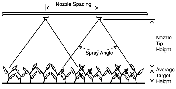
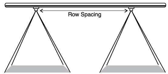
Table 4. Minimum suggested spray heights.

Spray
Angle
Nozzle Height
20"
Spacing
30"
Spacing
40"
Spacing

*Not recommended

**Nozzle angled 35°­–45° to vertical

65°22–24"33–35"NR*
80°17–19"26–28"NR*
110°12–14"16–18"NR*
120°14–18"**14"**14–18"**

“Even” Flat Fan Spray Nozzles

“Even” flat-fan nozzles apply a uniform coverage across the entire width of the spray pattern (Figure 18). They should be used for banding pesticides over the row and should be operated between 30 and 40 PSI. This nozzle should not be used for broadcast applications. The width of the band is dependent upon the nozzle height above the target and spray pressure, as shown in Table 5.

Table 5. Height for banding with even flat fan nozzles.

Band WidthApproximate Spray Height
40° Series80° Series95° Series
8"11"5"4"
10"14"6"5"
12"16"7"6"
15"20"9"8"

Flooding Fan Nozzle

Flood fan nozzles produce a wide-angle, flat-spray pattern and are used for applying herbicides and mixtures of herbicides and liquid fertilizers. The nozzle spacing for applying herbicides should be 60 inches or less. These nozzles are most effective in reducing drift when they are operated within a pressure range of 10 to 25 PSI. Relative to flat-fan nozzles, pressure changes have a greater impact on spray pattern width of flood nozzles. Also, the distribution pattern is not as uniform as that of the regular flat-fan nozzle. The best distribution is achieved when the nozzle is mounted at a height and angle to obtain at least 100% overlap (double coverage). When set for 100% overlap, a change in nozzle pressure distorts the spray pattern.

A “turbo floodjet” nozzle from TeeJet Technologies produces larger drops and a more uniform spray pattern than a standard flood tip. It is designed to reduce drift and provides uniform deposition with 30% to 50% overlap instead of 100% required by standard flood nozzles. The turbo flood nozzle is designed for use with soil-incorporated herbicides and liquid fertilizer and can be operated at pressures ranging from 10 to 40 PSI.

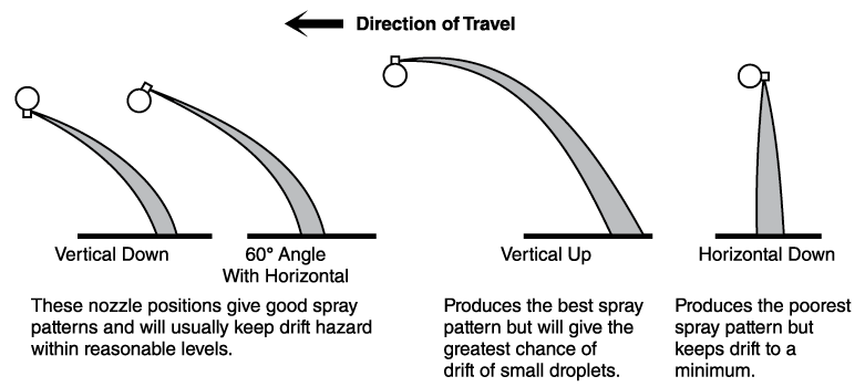
Flood nozzles can be mounted so they spray straight down, straight back or at any angle in between (Figure 19). Studies indicate the most uniform pattern is obtained when the spray is directed straight back, but this will produce the greatest chance for drift of the small droplets. Directing the spray straight down will minimize the drift potential but will produce the most irregular spray pattern. The best compromise position is to set the nozzle at a 45-degree angle with the sprayed surface. Care should be taken so that incorporation equipment does not intercept or interfere with the spray discharge pattern.

Hollow Cone Nozzles

Hollow cone nozzles are designed for air blast spraying or for directed sprays in a banded application and are used in situations where complete coverage of the leaf surface is important, such as with insecticides or fungicides. The hollow cone pattern provides a fine spray pattern, which achieves thorough coverage only when directed toward the target or combined with air assist. These nozzles usually operate in the pressure range of 40 to 100 PSI or more, depending on the nozzle being used and the pesticide applied. Spray drift is higher with hollow cone nozzles than with other nozzles, as small droplets are produced.

A hollow cone nozzle produces a spray pattern with more of the liquid concentrated at the outer edge of the pattern (Figure 15) and less in the center. Any nozzle producing a cone pattern, including the whirl-chamber type, will not provide uniform distribution for broadcast applications.

“Raindrop” nozzles from Delavan feature a wide-angle, hollow cone, drift-reduction design that produces large drops at pressures of 20 to 60 PSI. Although featuring a hollow cone design, these nozzles are designed to replace conventional flood nozzles in broadcast applications.

Full Cone Nozzles

The full cone nozzle produces a swirl and a counter swirl inside the nozzle that results in a full cone pattern. Full cone nozzles produce large, evenly distributed drops and high flow rates. A wide full cone tip maintains its spray pattern over a range of pressures and flow rates. It is a low-drift nozzle and is often used to apply soil-incorporated herbicides.

Figure 19
Photo Credit:
NDSU Photo
Various positions for mounting flood nozzles.

Nozzle Adjustment Problems

For broadcast application, flat-fan nozzles should be properly spaced and adjusted on the sprayer. Nozzle discharge angle, nozzle distance from the sprayed surface and nozzle spacing on the boom must all be considered for good spray coverage. Refer to Table 4 for proper nozzle adjustments. Figure 20 shows some of the spray pattern problems that may result from common boom adjustment errors.

Other Pesticide Application Equipment

Wiper Applicators

Several types of wiper applicators are available commercially. One consists of a long horizontal tube or pipe (3 to 4 inches in diameter), which is filled with a systemic herbicide (Figure 21). A series of short, overlapping ropes or a wetted pad on the tube is in contact with the herbicide and becomes saturated by wicking action. Another type is the roller applicator, which consists of a tube 8 to 12 inches in diameter turned by a hydraulic motor. The tube is covered with carpet that is continuously wetted. These units are mounted on the front or rear of a tractor on a three-point hitch that is hydraulically adjusted so it can be set at a height where the pad applies herbicide to weeds taller than the crop but does not contact the crop. Best results are obtained with double coverage of wiper applicators. The second pass should be in the opposite direction to the first pass so two sides of the plant are covered.

Direct Injection Sprayers

Direct injection sprayers continuously meter concentrated pesticide into the spray system as needed. They contain a large main tank and pump, for water or other carrier, and one or more smaller tanks and pumps for concentrated pesticide. Modern systems automatically adjust chemical injection flow rates to maintain proper per-acre application rates regardless of ground speed or active boom sections. However, users must ensure that chemical pump capacity is great enough to support desired ground speeds at their desired per-acre application rates. High-capacity pumps will allow for faster ground speeds.

The advantage of direct injection sprayers is that no mixed chemical is left over when the application is complete. These units may also be used to reduce pesticide costs by targeting pesticide applications within a limited portion of a field, such as border sprays of insecticide introduced during postemergence herbicide applications. The number of pesticides available for a given application depends on the number of installed product tanks, however, as each pesticide concentrate should be stored in its own tank. Mixing multiple pesticides in a single injection tank is a risky practice due to the potential for physical and chemical incompatibility.

One problem with injection sprayers is the timely injection of the chemical into the system so that it is discharged at the proper time. Lead time on injection may vary due to the size of the hoses on the sprayer, travel speed, the amount of liquid being applied and the point of injection of the chemical into the system. Direct injection requires precise measuring equipment that is maintained in good condition. Remember, it is more difficult to measure a small amount of chemical on a continuous basis than to measure one larger quantity and mix it into the spray tank.

Spray Monitors

Spray monitors may be of two types: nozzle flow monitors and system monitors. A nozzle flow monitor will alert the operator to a partially or fully blocked nozzle or a worn nozzle in an overflow condition, so that corrections can be made.

System monitors detect the overall operating conditions of the sprayer. They are sensitive to variations in travel speed, pressure and flow rate. These values, along with operator input such as swath width and gallons of spray in the tank, are fed to a computer that calculates and displays the travel speed, pressure and application rate. The monitor can also calculate and display other information such as the machine capacity in acres per hour, the acres covered, the remaining mix in the tank and the distance covered. To function properly, the monitor must have suitable sensors that are accurately and regularly calibrated. Spray system monitor functionality is oftentimes integrated into a multifunctional in-cab display, but standalone units also exist (Figure 22).

Some monitors can also automatically control the flow rate and pressure to compensate for changes in speed or flow. The automatic flow rate controller will respond if there is a deviation of the monitored rate from the desired flow rate. Flow compensation is usually done by changing the pressure setting within a certain range. If the controller is not able to bring the application rate back to the programmed flow rate for some reason, such as an excessive speed change or problems with the spray system, the unit will signal the operator that a problem exists. Monitors are helpful in precise chemical application work and should result in better pest control, more efficient spray distribution and reduced chemical cost.

Swath Markers

Although rendered obsolete in most situations due to the prevalence of satellite-based guidance, foam and dye marker systems can be used to aid uniform spray application by marking the edge of the spray swath (Figure 23). This mark shows the operator where to drive on the next pass to reduce skips and overlaps, and it is a tremendous aid in non-row crops, such as spraying tilled fields for applying pre-emergent pesticides. The mark may be continuous or intermittent. Typically, 1-2 cups of foam are dropped every 25 feet. The foam or dye requires a separate tank and mix, a pump or compressor, a delivery tube to each end of the boom and a control to select the proper boom end. Another marker is the paper type. This unit drops a piece of paper intermittently over the length of a field. The paper may blow across the field unless it can be anchored by applying some moisture from the sprayer to the paper.

Global Navigation Satellite System

Global Navigation Satellite System (GNSS) is the collective term for the four fully operational positioning satellite constellations with global coverage (Figure 24). The Global Positioning System (GPS), developed by the U.S. Department of Defense, was the world’s first GNSS constellation and remains the best-known. Others are BeiDou (China), Galileo (European Union) and GLONASS (Russia).

Signals from three GNSS satellites are required to determine a two-dimensional position on the earth. Altitude determination requires a signal from a fourth satellite. A GNSS receiver interprets the signals sent from one or more GNSS constellations and computes its position. GNSS positioning is now commonplace in aerial and ground pesticide application, as it enables equipment guidance, accurate swath spacing and automatic boom sectional control.

Equipment Guidance Systems

Lightbar guidance and automated steering systems help maintain precise swath-to-swath widths. Guidance systems identify an imaginary A-B starting line, curve or circle for parallel swathing using GNSS positions and a control module. The module accounts for the swath width of the implement and then uses GNSS to guide machines along parallel, evenly spaced swaths. These swaths may be straight, curved or circular. Lightbar guidance systems include a display module that uses audible tones or lights as directional indicators for the operator. The guidance system allows the operator to monitor the lightbar to maintain the desired distance from the previous swath.

Guidance systems require two principal components: a light bar or screen, which is essentially an electronic display showing a machine’s deviation from the intended position (Figure 25), and a GNSS receiver for locating the position. This receiver must feature a suitably rapid position refresh rate (usually 5 or 10 times per second) to enable equipment guidance. GPS receivers designed for guidance can be used in conjunction with a yield monitor or for other positioning equipment.

Automated steering systems integrate GPS guidance capabilities into the vehicle’s steering system. In addition to following an A-B starting line, modern systems feature capabilities such as automated end-of-row turns and the ability to establish a custom pattern based on your initial pass.

Automatic Sectional Control

The advent of GNSS guidance has enabled automatic sectional control for sprayers (Figure 26). A sprayer equipped with automatic sectional control uses GNSS data from the guidance system to automatically shut off boom sections when they enter previously sprayed areas or designated no-spray zones, such as grassed waterways. This prevents chemical overapplication, which saves money, increases efficiency and minimizes crop injury.

The degree of chemical savings achieved with automatic sectional control depends on field shape and the number of sprayer boom sections. A greater number of boom sections will lead to greater savings. Irregularly shaped fields will yield greater savings than square or rectangular fields.

Shielded or Hooded Boom

Shielded or hooded (completely covered) spray booms increase spray deposition in the target swath when used on broadcast sprayers (Figure 27). Studies show that shielded booms and individual nozzle shield cones can reduce spray drift by 50% or more. Qualified hooded/shielded sprayers are a drift reduction technology according to the EPA. Certain pesticides, depending on their label language, are eligible for reduced use restrictions when using a qualified sprayer. However, shields and hoods DO NOT eliminate all drift; they only reduce the amount. Be aware of susceptible crops downwind, and use caution when spraying. Be sure to check with the state department of agriculture or enforcement agency for state pesticide laws to be sure they allow spraying during strong wind conditions when shields or hoods are used.

The main disadvantages of shielded or hooded booms are poor nozzle visibility in case of plugs, the increased weight that must be carried on the boom and the added cleanup when different pesticides are going to be applied with the sprayer. Sprayer cleanup should be done in the field or on a sprayer mixing/loading pad that collects washwater so that the rinsate can be contained and used as makeup water for future spraying jobs.

Air Assist Sprayers

Air assist sprayers inject sprayed pesticide into a high-speed air stream, which helps deliver the spray to the crop and gives better penetration of the crop or weed canopy (Figure 28). Studies show that air assist sprayers can carry spray droplets deeper into the plant canopy and help deposit more pesticide on the underside of the crop or weed leaves compared to other sprayers, which may improve pest control.

NDSU studies showed that, at the same application rate, air assist sprayers improved leaf coverage by about 5% over conventional sprayers in a full potato plant canopy.

Air assist sprayers may have a high drift hazard early in the growing season when the plant canopy is small. This is due to dissipation of the air blast when hitting the ground, as the resulting upward rebound of the air that can carry the small spray drops up to drift away. It is recommended to reduce the air velocity in small or young crop canopies due to drift risk, but it can be difficult to achieve the proper settings. Spray drift hazard is considerably lower when used to apply pesticides to full plant canopies later in the growing season.

Pulse Width Modulation

Maintaining a constant application rate when ground speed fluctuates is a fundamental concern when applying pesticides. Pulse-width modulation (PWM) sprayers provide rate control by changing the intermittent on/off cycling of an electronically actuated solenoid valve mounted upon each nozzle body. Application rate is modified by altering the duty cycle, which is expressed as the percentage of time that the nozzle remains on. Cycling occurs so rapidly, typically at 10 to 30 Hz (1 Hz = 1 cycle per second), that spray pattern and quality are not affected.

The primary benefit of a PWM sprayer is that the operator’s chosen droplet size will be consistently applied throughout the field, as flow rate changes do not require pressure adjustments. This contrasts with a sprayer rate controller, which modifies nozzle flow rate in response to fluctuating ground speed by adjusting system pressure, which in turn alters droplet size. Additional benefits of PWM sprayers include turn compensation, individual nozzle sectional control and faster nozzle shutoff response.

For more information on PWM sprayers and their use, refer to UGA Cooperative Extension Circular 1277: Pulse Width Modulation Technology for Agricultural Sprayers or the Sprayers101 article Rate Controllers and a Pulse Width Modulation Update.

Sense-and-Act Sprayers

Sense-and-act sprayers use sensors to detect the presence of weeds along the spray boom and send an activation signal to the nozzles when weeds are detected (Figure 29). Green-on-brown systems detect green vegetation against a soil background, such as in fallow, and have been commercially available in the U.S. since the early 2000s. Contemporary examples include Trimble Weedseeker 2 and WEED-IT Quadro. Green-on-green systems, such as John Deere See & Spray or Greeneye, detect weeds within a growing crop and were released commercially within the U.S. in 2022.

Sense-and-act sprayers offer numerous opportunities for weed management but require careful consideration of sprayer configuration. Settings requiring configuration include weed detection sensitivity, nozzle selection, spray length when a nozzle is activated and the choice of single-nozzle activation, where only the nozzle in the weed’s lane is turned on, versus overlapping-nozzle activation, where one adjacent nozzle on each side is also turned on. Configurations that minimize product usage, such as using an even-spray nozzle with single-nozzle activation and a short spray length, leave little room for error in assuring that each detected weed is effectively sprayed. It is infeasible to simultaneously maximize weed control and minimize product usage; achieving one will require compromising the other.

Spray Drones

Although well-established internationally, particularly in Southeast Asia, spray drones (Figure 30) are an emerging technology in North Dakota and across North America. Advantages of spray drones include their lower cost relative to large ground sprayers and their ability to apply products when landscape characteristics or field conditions do not allow ground travel. Disadvantages of spray drones include their limited capacity and productivity relative to large ground sprayers and uncertainties around spray drift and application efficacy.

Research is ongoing to better understand the spray application characteristics of drones. Drone sprays, consisting of relatively small droplets that are highly concentrated due to low carrier volume (e.g., 1 to 3 gpa) and delivered to the target by air assist generated from propellor downwash, are substantially different than those delivered by a ground sprayer. Studies suggest that obtaining a consistent and uniform spray pattern with a drone is challenging, as propellor downwash tends to concentrate spray directly beneath the vehicle while also causing considerable lateral movement of spray droplets. Relatedly, characterizing spray drift from drones is another research focus.

Due to the characteristics of drone sprays, it is critical for drone spray operators to calibrate their drones for effective swath width. Failure to do so may lead to within-field striping due to inadequate coverage caused by overestimating the effective swath width. Swath width calibration is best performed within the crop canopy, as vegetation characteristics modify the movement and deposition of spray droplets. Further details on calibrating a drone can be found in the Sprayers101 articles How to Calibrate a Drone and RPAS Swathing in Broad Acre Crop Canopies.

Spray drone operators must also meet all applicable state and federal licensing and operational requirements for unmanned aerial application, which are more extensive than those for ground application of pesticides.

Spray Drift

Drift of pesticides away from the target is an important and costly problem facing applicators. In addition to the potential damage to nontarget areas, drift tends to reduce the effectiveness of chemicals and costs money. Drift can occur by two different means.

VAPOR DRIFT occurs when a chemical vaporizes after being applied to the target area. The vapors are then carried to another area where damage may occur. The amount of vaporization depends largely on the air temperature and formulation of the pesticide being used. Some products may vaporize rapidly at temperatures as low as 40 degrees Fahrenheit. “Low volatile” esters of 2,4-D or MCPA may vaporize at 75-90 degrees F. The amine formulations of 2,4-D or MCPA are essentially “nonvolatile.” The dangers of vapor drift can be reduced substantially by choosing the correct herbicide formulation.

PHYSICAL DROPLET DRIFT is the actual movement of spray particles away from the target area. Many factors affect physical drift, but one of the most important is droplet size. Small droplets fall through the air slowly, so they are carried farther by air movement.

Liquid sprayed through a nozzle divides into droplets that are spherical or nearly spherical in shape. The recognized measurement for indicating the size of these droplets is in microns.

Droplets smaller than 100 microns are usually considered highly prone to drift. Drops this size are so small that they cannot be easily seen unless in extremely high concentrations, such as on a “foggy” morning.

All spray droplet atomizers available today produce a range of droplet sizes. Some produce a wider range than others. Table 6 shows a typical distribution of droplet sizes for a flat-fan nozzle when spraying water at two different pressures. Most of the droplets produced from a hydraulic spray nozzle are small. Table 6 indicates that more than half of all the droplets were less than 63 microns in diameter at 20 or 40 PSI. However, little of the total volume is contained in droplets with a diameter of less than 63 microns. Most of the volume is contained in the larger droplets, particularly those ranging in size from 63 to 210 microns. These principles hold true for both pressures, although increasing the pressure caused more of the spray to be contained in small droplets. Even though the volume of small droplets is low, downwind crops can be seriously affected if the crop is susceptible to injury from the pesticide.

Table 6. Droplet size range for a flat fan nozzle at 20 PSI and 40 PSI.

Size Range,
microns
Percent of
All Droplets
Percent of
Total Volume
20 PSI40 PSI 20 PSI40 PSI
0-2122.444.6 0.10.4
21-6337.639.5 3.010.4
63-10521.210.0 10.720.1
105-1479.23.8 16.225.4
147-2107.21.9 36.735.3
210-2942.30.2 27.57.7
over 2940.20.0006 5.80.7

The number of droplets deposited per square inch of surface from the ordinary spray nozzle is normally far more than the minimum required to control a specific pest. In some situations, particularly when using fungicides or insecticides, high spray droplet density may be needed. Table 7 shows that coverage or density of droplets on a surface can be theoretically achieved with uniform droplets of various sizes when applied at 1 gallon per acre. Decreasing the drop size from 200 to 20 microns will increase coverage 10-fold. Results of many studies indicate that spray density required for effective weed control varies considerably with plant species, plant size and condition as well as herbicide type, additives and carrier used. Table 7 shows that drop density decreases for drops above 200 microns in diameter at low application rates. Although excellent coverage can be achieved with extremely small drops, decreased deposition and increased drift potential limit the minimum size drop that will provide effective pest control.

Drift potential of various-sized drops under ideal atmospheric conditions for spraying (Delta T = 14.3°F) is also shown in Table 7. A nonevaporating 100-micron droplet will move 48 feet horizontally in a 3-mile-per-hour breeze while falling 10 feet. Drops under 50 microns are nearly invisible in the air and can remain suspended for long periods of time. The objective in applying pesticides is to achieve uniform spray distribution while retaining all the spray droplets within the intended spraying area.

Table 7. Spray droplet size and its effect on coverage and drift.

Droplet
Diameter
(microns)
Type of
Droplet
1 gal/A ApplicationDrift
Distance in
10 ft. Fall
With 3 mph Wind (ft)
Droplets
Per In²
(No.)
Coverage Relative to 1000 Micron Drops
*Delta T = 14.3°F (air temperature of 86°F and 50% relative humidity)
5Dry Fog9,220,00020015,800
10 1,150,0001004.500
20Wet Fog144,000501,109
50 9,22020178
100Misty Rain1,1501048
150 342725
200Light Rain144515
500 927
1000Heavy Rain115

Spray liquid may have a velocity of 60 feet per second or more when leaving a nozzle. The speed is reduced due to air resistance and the spray material breaking into small drops. Table 8 shows, under atmospheric conditions that encourage rapid droplet desiccation (Delta T = 20.3 degrees F), the distance in which droplets will decelerate to a free fall condition and the length of their life before they disappear due to evaporation. For example, water droplets less than 20 microns in diameter will evaporate in less than one second while falling less than one inch. Droplets over 100 microns in size resist evaporation much more than smaller droplets due to their larger volume-to-surface area ratio.

Table 8. Evaporation and deceleration of various size droplets*.

Droplet Diameter (microns)Deceleration Distance
(in)
Terminal Velocity
(ft/sec)
Time to Evaporate (sec)Fall Distance (in)Final Drop Dia. (microns)
*Conditions assumed: Delta T = 20.3°F (air temperature 90°F, 36% relative humidity), 25 PSI, 3.75% pesticide solution
20>10.040.3<17
5030.251.8317
10090.9179633
150161.71648050
200252.4291,51267

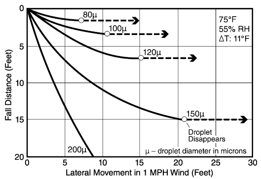
With water carriers, spray droplets will decrease in size due to evaporation during their fall. Figure 31 shows the trajectories of evaporating spray droplets falling through stable air under ideal atmospheric conditions for spraying (Delta T = 11 degrees F) in a 1-mile-per-hour crosswind. Droplets smaller than 100 microns obtain a horizontal trajectory in a very short time, and the water in the droplet disappears. The active ingredients in these droplets become very small aerosols, most of which will not reach the ground until picked up in falling rain. Figure 31 illustrates that there is a rapid decrease in drift potential of droplets as they increase to about 150 or 200 microns. The minimum droplet size to effectively reduce drift potential depends on wind speed but generally lies in the range of 150 to 200 microns for wind speeds of 1 to 7 miles per hour. For typical ground applications of herbicides with water carriers, droplets of 50 microns or less will completely evaporate to a residual core of pesticide before reaching the target. Droplets greater than 150 microns will have no significant reduction in size before deposition on the target. Evaporation of droplets between 50 and 150 microns is significantly affected by temperature, humidity and other climatic considerations.

Figure 31
Photo Credit:
NDSU Photo
Evaporation rate of water droplets.

Although drift does not always cause clear and obvious harm, preventing drift is the legal responsibility of the applicator and should be a top priority. Also, keep in mind that if you have considerable drift downwind, you will be losing pesticide. Drift should be kept to a minimum, and all drift-reducing techniques should be used if the chemical permits.

Several factors affect droplet size and potential drift:

  1. Wind direction
  2. Wind speed
  3. Air stability
  4. Spray pressure
  5. Nozzle type
  6. Flow rate
  7. Nozzle spray angle
  8. Boom height
  9. Relative humidity and temperature
  10. Drift reduction adjuvants
  11. Pesticide formulation
  12. Shielded booms

Wind direction: Pesticides should not be applied when the wind is blowing toward an adjoining susceptible crop or to a crop in a vulnerable stage of growth. Wait until the wind blows away from any susceptible crops, plants or sensitive areas downwind.

Wind speed: The amount of herbicide lost from the target area and the distance it moves both increase as wind velocity increases. However, severe drift injury can also occur with low wind velocities, especially under temperature inversion conditions.

Air stability: Air movement largely determines the distribution of spray droplets. Wind is generally recognized as an important factor, but vertical air movement is often overlooked. Temperature inversion is a condition where cool air near the soil surface is trapped under a layer of warmer air aloft. A high inversion potential occurs when ground air is 2 to 5 degrees Fahrenheit cooler than the air above. Under inversion conditions, little vertical mixing of air occurs, even with a breeze. Inversions can often be identified by observing smoke from a fire or smokestack. Smoke moving horizontally close to the ground would indicate a temperature inversion.

Spray drift often occurs, even with relative calm wind conditions, under stable air or an inversion condition. Spray drift injury can be severe since small spray droplets may fall slowly or remain suspended due to the cool, dense air and then move with a gentle breeze into an adjoining area. Some of the most severe drift problems have occurred with low wind velocities, inversion conditions and small spray droplets. Avoid spraying under inversion conditions. For more information, refer to NDSU Extension publication AE1705: Air Temperature Inversions: Causes, Characteristics and Potential Effects on Pesticide Spray Drift.

Another cause of spray drift is from “lapse” being greater than a 3.2 degrees F decrease per 1,000 feet of altitude. Under a normal “lapse” situation, cool air gently sinks, displacing lower warm air and causing vertical mixing of air. This may cause small droplets to be carried aloft and dispersed. When the “lapse” is stronger, more spray will be carried upward, causing a greater chance for spray drift. Research has shown that temperature inversion causes more spray drift than “lapse” conditions at a given wind speed.

Spray pressure: Spray pressure influences the formation of droplets from the spray solution. The spray solution emerges from the nozzle in a thin sheet, and droplets form at the edge of the sheet. Higher pressures cause the sheet to be thinner, and this sheet breaks up into smaller droplets. Large nozzles with higher delivery rates produce larger droplets. Small droplets are carried farther downwind than the larger droplets formed at lower pressures. Table 9 shows the percentage of chemical deposited downwind at various distances. It also shows the distance downwind at which the chemical deposition rate decreases to 1% of the application rate.

Table 9. Comparison of the distances downwind for 1 percent of the application rate to be deposited.

Run No. and ComparisonPressure, PSIWind Speed, mphPct. Deposited atDownwind Distance,
ft.*
4 ft.8 ft.
Regular flat fan
at 14” height
403.53.10.67
Regular flat fan
at 27” height
40 5.91.513
Regular flat fan
at 25 PSI
259.910.33.115.5
Regular flat fan
at 40 PSI
40 9.13.617
Regular flat fan
at 18”
305.39.32.214
Low-pressure flat fan at 18”15 5.71.411
Regular flat fan and 6 oz. Nalco-Trol308.23.30.57
Regular flat fan with no thickner30 8.33.116.5
Flooding flat fan
at 13”
104.21.30.65.5
Regular flat fan
at 18”
30 3.51.19
Raindrop nozzle
at 18”
4010.34.80.67
Regular flat fan
at 18”
30 10.23.316
*Downwind distance for deposit to drop to 1% of application volume.

Nozzle type: Droplet sizes produced by various nozzle types at different spray pressures are shown in Table 10. Flat-fan and flood nozzles produce similarly sized droplets. The full cone nozzle produces larger droplets than the flat fan, while the hollow cone nozzle produces smaller droplets than the flat fan.

Table 10. Effect of nozzle type on droplet size.

Nozzle Type
(0.5 GPM flow at 40 PSI)
Nozzle Pressure
15 PSI40 PSI60 PSI
(volume median diameter in microns)
STD. 80° Flat Spray tip360330
Ext. Range 80° Flat Spray Tip460370340
Flood Spray Tip580450420
Full Cone Tip1090680
Hollow Cone Tip260230

Flow rate: Nozzle flow rate has a large effect on drop size (Table 11). Nozzles with small orifices produce small drops while large nozzles produce larger drops. Increasing nozzle size to the next step up in size is an excellent way to reduce the number of driftable fines.

Table 11. Effect of flow rate on droplet size.

Nozzle Type
(40 PSI pressure)
Nozzle Flow Rate
0.2 GPM0.5 GPM0.8 GPM
(volume median diameter in microns)
STD. Flat Spray Tip260360440
Ext. Range 80° Flat Spray Tip270370450
Flood Spray Tip370450510
Full Cone Spray Tip680770
Hollow Cone Tip200260

Nozzle spray angle: Spray angle is the interior angle formed between the outer edges of the spray pattern from a single nozzle. Table 12 shows that nozzles with wider spray angles will produce a thinner sheet of spray solution and smaller spray droplets than a nozzle with the same delivery rate but a narrower spray angle. However, wide-angle nozzles are placed closer to the target than narrow ones, and the benefits of lower nozzle placement outweigh the disadvantage of slightly smaller droplets.

Table 12. Effect of spray angle on droplet size with flat fan nozzles.

Spray
Angle (degrees)
Nozzle Type
(at 40 PSI)
Nozzle Pressure
15 PSI40 PSI60 PSI
(volume median diameter in microns)
40°0.5 GPM Flat Spray900810780
65°0.5 GPM Flat Spray600550530
80°0.5 GPM Flat Spray450360330
110°0.5 GPM Flat Spray390310290

Volume median diameter (VMD) is a term used to describe the droplet sizes produced from a nozzle. VMD is defined as the diameter at which half the spray volume is in droplets of larger diameter and the other half of the volume is in smaller droplets.

Boom height: Operating the spray boom as close to the sprayed surface as possible is a good way to reduce drift. The closer the boom is to the ground, the wider the angle the spray discharge must be to give uniform coverage. Be sure nozzles are right for the application. Booms that bounce will cause uneven coverage and drift. Wheel-carried booms are a good way to stabilize boom height, which will reduce the drift hazard and produce a better spraying job.

The effect of reducing drift when nozzles are mounted as close to the ground as possible is shown in Table 9. Chemical discharged from the flat-fan nozzle shows a considerable reduction in downwind deposits at both the 4- and 8-foot distances for the lower-positioned nozzles. Flood nozzles produce a wide spray pattern and can be operated at low pressures. The wide pattern allows them to be mounted close to the ground, keeping drift to a minimum.

Relative humidity and temperature: Low relative humidity and/or high temperature conditions cause faster evaporation of spray droplets between the sprayer and the target. Evaporation reduces droplet size, which in turn increases the potential drift of spray droplets. Spraying during lower temperatures and higher humidity conditions will help reduce drift. Delta T accounts for temperature and humidity in a single value that describes the evaporative capacity of the air; values from 3.6 to 14.4 degrees F are ideal for spraying.

Drift reduction adjuvants: Some spray adjuvants act as drift reduction agents. By increasing the viscosity of the spray solution or otherwise modifying the spray solution, these materials increase the number of larger droplets and decrease the number of fine drops. These products reduce drift but do not eliminate it. Table 9 shows the reduction in downwind deposits when using Nalco-Trol, a drift reduction adjuvant.

Pesticide formulation: Droplets formed from an oil-based carrier tend to drift farther than droplets from a water carrier because oil droplets are usually smaller and lighter, and they remain airborne for a longer period. For sprays produced with the same hydraulic nozzle and the same spray pressure, oils form into smaller droplet sizes than water. Oil-based sprays also evaporate more slowly than water-based sprays, so drops remain active for a longer time.

Shielded booms: Wind during the spraying season is often a limiting factor to timely spraying in North Dakota. Studies show that shielded booms can reduce drift by 50% or more. Shields help extend the spraying time under moderate winds. Spraying must be stopped when winds are too strong or when susceptible crops are downwind. Shields do not stop all drift; they only reduce it. Major drift problems can result when using shields if applicators are careless by not paying attention to downwind crops.

Drift Control

Because all nozzles produce a range of droplet sizes, the small, drift-prone particles cannot be eliminated. However, drift can be reduced and kept
within reasonable limits.

  1. Use the largest nozzle size compatible with your application. Larger nozzle orifices produce larger droplets, which are less prone to drift.
  2. Use adequate amounts of carrier. This necessitates larger nozzle sizes, which produce larger droplets. Although this will increase the number of refills, the added carrier improves coverage and usually increases pesticide effectiveness.
  3. Avoid using high pressure. Higher pressures create fine droplets. Plan to operate nozzles near the middle of their rated pressure range.
  4. Use a drift-reducing nozzle where practical. They produce larger droplets and fewer driftable fines than the equivalent flat-fan nozzle.
  5. Use a drift-reducing adjuvant. The CPDA Certified Adjuvant Products List contains over two dozen such products.
  6. Use wide-angle nozzles and keep the boom stable and as close to the crop as possible.
  7. Spray when wind speeds are less than 10 mph and when wind direction is away from sensitive crops.
  8. Do not spray when the air is completely calm or when an inversion exists.
  9. Use a shielded spray boom when wind conditions exceed prime pesticide application conditions.

Calibrating Chemical Applicators

The amount of chemical solution applied per acre depends on forward speed, system pressure, nozzle size and nozzle spacing on the boom. A change in any one of these will change the application rate.

The forward speed and pressure must be adjusted correctly to set the sprayer for any given per-acre rate. The nozzle size should be changed to make a large change in application rates, and all nozzles should discharge an equal amount of spray. If any of these adjustments are incorrect, poor results will be obtained.

The first thing to accomplish with sprayer calibration is to select the nozzle type and size appropriate for your spraying task. You can base the nozzle type decision on spraying conditions and guidelines as recommended in Tables 2 and 3.

Once you’ve selected the type of nozzle, the next step is to calculate the nozzle size.

Nozzle selection should not be based on “gallons per acre” as advertised by some manufacturers. A nozzle that is identified as a 10-gallon nozzle will deliver this amount per acre only for one specific condition, such as when the nozzle spacing is 20 inches on the boom, the sprayer is traveling at 4 mph and the boom pressure is 30 PSI. If the spacing, speed or pressure varies from these set values, the nozzle will not deliver the specified gallons per acre.

Choice of nozzle size should instead be based on a gallons-per-minute calculation. Basing calculations on gpm allows the operator to make spraying decisions based on the crop and field conditions.

Calibration Method No. 1

Equation 1

gpm = gpa x mph x w / 5940

gpm = gallons per minute, the nozzle flow rate.

gpa = gallons per acre, a decision made based on label recommendations, field conditions, spray equipment and water supply.

mph = the ground speed you select, miles per hour.

w = band width or spacing between nozzles in inches.

5940 = a constant to convert gallons per minute, miles per hour and nozzle spacing in inches to gallons per acre.

As an example, assume you are going to use 80-degree flat-fan nozzles. You desire to apply 20 gallons per acre, nozzles are spaced 20 inches apart and the speed you prefer to drive is 6 mph. What size nozzle in gallons per minute is needed for this spray application?

gpm = 20 gpa x 6 mph x 20 inches / 5940

gpm = 0.4 gallons per minute per nozzle

Specifications from manufacturers’ catalogues for fan nozzles (Table 13) show that the XR8004 and AIXR11004 will provide 0.4 gallons per minute at 40 PSI. Another choice is the XR8005 or AIXR11005 at 25 PSI, or the XR8006 or AIXR10006 at 18 PSI. The lower pressures will provide larger drops with less drift potential than spraying at 40 PSI. The AIXR nozzle will produce larger droplets than the XR nozzle at all pressures. However, larger drops will reduce coverage as compared to smaller drops. Be sure to check the pesticide label for instructions on suitable nozzle types and operating pressures.

Table 13. Fan nozzle output.

Fan Nozzle*PressureGallons Per Minute

80° or 110° fan, 20-inch spacing

*The XR and AIXR nozzles are Spraying System Co./TeeJet

XR8002 or15.12
AIXR1100220.14
30.17
40.20
XR8003 or15.18
AIXR1100320.21
30.26
40.30
XR8004 or15.24
AIXR1100420.28
30.35
40.40
XR8005 or15.31
AIXR1100520.35
30.43
40.50
XR8006 or15.37
AIXR1100620.42
30.52
40.60

Once you have determined the proper size tip, put these nozzles on the sprayer and operate it with water. Test for leaks, other sprayer problems, spray pattern uniformity and calibration.

Equation 2

If a set of nozzles is available for use, the previous formula, after rearranging the values, can be used to determine the sprayer application rate in gallons per acre.

gpa = gpm x 5940 / mph x w

Example: What is the application rate in GPA of a sprayer with the following parameters:

  • 0.2 gpm flow rate
  • 20-inch nozzle spacing
  • 6 mph travel speed

gpa = 0.2 gpm x 5940 / 6 mph x 20 in = 9.9

Sprayer calibration is extremely important, as it ensures that pesticide is being applied uniformly and at the correct rate. Sprayers must be calibrated even when new or when nozzles are replaced. They should also be recalibrated after a few hours of use, as new nozzles wear and flow rate will increase rapidly. Calibration should be done by measuring the amount of pesticide applied to a part of an acre and calculating how much would be applied to an entire acre. Be sure to check the flow rate of all nozzles on the sprayer so they are all applying the same amount. Each nozzle is spraying a separate strip through the field. If one nozzle is applying more or less than it should, streaking due to under- or overapplication may occur.

Operate the sprayer using the same throttle setting you use when spraying and when making the speed check. This will ensure the pump is delivering the same volume as it will when you’re spraying.

Catch the spray material from each nozzle in a measuring container for one minute. Carefully measure the discharge from each nozzle. It is usually easier to make measurements in ounces per minute rather than gallons per minute. Multiply the gallons per minute flow rate given in a nozzle catalog by 128 to convert it to fluid ounces per minute. Many nozzle catalogs also list flow rate in ounces per minute as well as gallons per minute.

Equation 3

1 gal = 128 ounces

In our example from Equation 1, we needed 0.4 gpm per nozzle.

0.4 gpm x 128 oz/gal = 51 oz/min

Compare this calculated number of ounces with the measured values. Any nozzles that are not within 5% of the average output should be cleaned if they’re plugged or replaced if worn. If an individual nozzle discharge rate exceeds the manufacturer’s specification by 10% or greater, it is worn out and should be replaced.

If the average output is less than is needed, adjust the output by raising or lowering the pressure. A simple and fast method to check nozzle flow rate is with the use of a nozzle flow calibrator, as shown in Figure 32. It is faster than collecting flow in a measuring container and very accurate.

Speed Check

An accurate speed is essential for good sprayer operation. Tractors or sprayers that use GPS or radar to measure ground speed should give accurate readings. Equipment that uses mechanical speedometers, such as older tractors or ATVs, does not give accurate readings, so they need to be checked. Use a tape measure to stake out a measured distance. Then record the time it takes to drive the loaded sprayer over this distance (Figure 33) at the throttle setting and the gearing that you will use for spraying. Do this with the sprayer at least half-full of water and on the same surface that will be sprayed – calibrating on loose soil or hard roads will not give accurate speeds when operating in fields.

Table 14. Seconds to drive 300 feet converted to miles per hour.

MPHSeconds to
Drive 300 Feet
MPHSeconds to
Drive 300 Feet
1.0204 8.026
1.5136 8.524
2.0102 9.023
2.582 9.522
3.068 10.020
3.558 10.519
4.051 11.018
4.545 12.017
5.041 13.016
5.537 14.015
6.034 15.014
6.531 16.013
7.029 18.011
7.527 20.010

Equation 4

speed (mph) = distance (feet) x 60 / time (seconds) x 88

A speed check over a 300-foot distance is accurate and easy to do. Table 14 converts the time (in seconds) to travel 300 feet into miles per hour.

Calibration Method No. 2

The following calibration method eliminates guesswork and enables you to quickly and accurately determine how the sprayer must be set up to deliver the GPA that you require. This method permits the sprayer to be set up and calibrated by operating the sprayer over a short distance in the field. It ensures that the nozzles will provide the uniform output that is needed.

This method involves spraying over a measured distance, starting with a full tank of water. Traveling over a longer distance will provide more accurate results.

This formula can be used to calibrate over any distance. This method works well when you have a field of a known length such as ½ mile (2640 feet) or 1 mile (5280 feet). Other distances of measured length can also be used.

1. Start with a full tank of water.

2. Spray a known distance in the field in
which you will be spraying.

3. MEASURE the gallons of water required
to refill the tank.

4. Use the following formula to figure gallons per acre (GPA).

GPA = Number of gallons to refill the tank x 43,560 ft2 ÷ acre / Width of boom coverage (ft) x distance of travel (ft)

Example: After spraying a ½ mile distance,

18.25 gallons are required to refill the tank. The sprayer covers a 50-foot swath.

GPA = 18.25 (gal) x 43,560 (ft2/ac)

50 (ft) x 2640 (ft)

GPA = 6

A good way to double-check your calibration is to determine how much pesticide was applied to a certain acreage.

For example, if 100 acres were sprayed and 600 gallons of chemical mix were used, this was an application rate of 6 gallons per acre. This system is very simple and has the advantage of measuring the amount of spray that was truly applied to an area. Keep in mind, this should not be your only calibration method.

Calibration Method No. 3

OUNCES = GALLONS METHOD

This method of calibration is very easy and can be used to check and fine-tune a sprayer quickly, but it does require driving a distance in the field. Before calibrating the sprayer with any method, you must check nozzle output for uniformity. Correct any nozzles that vary in flow rate by more than ±5%. Also check that the pressure gauge is reliable and that the pressure is properly set. Then proceed as follows:

1. For broadcast application, determine the distance, in inches, between nozzles. For banded applications, determine the band width in inches. For directed applications, collect the discharge from all nozzles per row.

2. From Table 15, determine the distance needed to equal 1/128 acre. Mark this distance off in a field you will be spraying.

3. Measure the time (in seconds) needed to drive the required distance at normal operating speed with all equipment attached and the spray tank ½ full.

4. Collect the discharge from all nozzles directing spray to one row for the time measured in step 3. All chemicals added together in ounces is gallons per acre. If broadcast spraying is being done, the ounces collected from one nozzle is gallons per acre.

Table 15. Calibration distance, ounces
to gallons, 1/128 acre.

Nozzle Spacing
or Band Width (inches)
Course Distance
(feet)
8510
10408
12340
14291
16255
18227
20204
22185
24170
26157
28146
30136
32127
34120
38107
40102

Band and Directed Spraying

Band aplication is applying a chemical in parallel bands, leaving the area between bands free of chemical.

Directed spraying is the application of a chemical to a specific area such as a plant canopy, a row or at the base of the plants.

Several nozzle configurations are often used when foliage penetration or row crop height presents a problem. Figure 34 shows several commonly used nozzle configurations.

The two- and three-nozzle configurations give better bottom leaf coverage than a single nozzle. This can be important with many pesticides. Drop nozzles are useful for herbicide application in taller row crops to reduce the risk of crop injury. In smaller row crops, a single nozzle “band” configuration using a nozzle with a uniform pattern, such as an even flow flat fan, should be adequate.

Band Application Calibration

The same calibration methods can be used to calibrate band applicators as were used for broadcast spraying. The only difference is the amount of area being covered. In band spraying, a treated acre refers only to the treated area in the band. Total acres refers to the entire acreage in the field, which includes the sprayed bands and the area between the bands. The spray that would be discharged on a broadcast rate is concentrated in a narrow band by the ratio of the row spacing divided by the band width (see the following example). In band spraying, the row spacing and the nozzle spacing are the same.

Unless otherwise specified, chemical application rates are given on a broadcast basis. For band applications, the rate per treated area is the same as the broadcast rate, but the total amount of pesticide used on a field is less because only a portion of the field is treated.

Spray discharge charts furnished by manufacturers for band nozzles are usually listed as applying chemical on a broadcast basis. The amount applied will increase when directed into a narrow band.

Band Calibration

1. Determine travel speed in the field you will be spraying. Drive at a uniform speed and measure the time to drive 300 feet.

2. Convert the time to travel speed in MPH from Table 14.

3. Check for nozzle uniformity, and if variation is more than 10% from the average, replace the nozzles. Determine the application rate in GPA by using one of the three calibration methods.

4. The answer is the application rate per
total acre.

5. Rate x row width (in) = Rate per treated acre

Total acre band width (in)

Example: In nozzle manufacturer charts, gallons per acre means volume applied to the area sprayed (treated acre). Depending on row spacing and band width, this area is some fraction of the total field. The following shows the higher volume discharged in a treated acre when the broadcast rate is determined:

  • 5 GPA measured with the broadcast calibration method
  • 30-inch row spacing
  • 10-inch band width

5 GPA x 30-inch row spacing / 10-inch band width = 15 GPA being applied in the band

As an alternative to calculating the conversion from a per-total-acre rate to a per-treated-acre rate, Table 16 shows the concentration effect of directing the spray from the broadcast rate to band application. Multiply the GPA found on the broadcast basis times the appropriate conversion factor in Table 16.

With 15 GPA being applied per treated acre (in the row), MIX THE CHEMICAL IN THE SPRAY TANK BASED ON THIS RATE. Do not mix it on the 5 GPA (total acre) rate or you will be applying chemical in the row at three times the desired concentration. If you do not want to apply water in the row at 15 GPA, select a smaller nozzle. Refer to the charts in the nozzle manufacturer’s catalog.

Table 16. Conversion factor to convert broadcast rate (rate per total acre) to band rate (rate per treated acre).

Band Width
(in.)
Row Spacing (inches)
20303640
82.53.84.55.0
102.03.03.64.0
121.62.53.03.3
141.42.12.62.9

Hand Sprayer Calibration

Hand sprayers are typically used for applying chemicals to small areas. Hand sprayers may be calibrated as follows:

  • determine the square feet in an area
  • measure the output of the spray gun for one minute
  • calculate how fast the measured area should be covered

Then, mix enough chemical to cover the area and apply all the chemical to the area as evenly as possible.

Example: You measure an area 21 feet by 21 feet. This is approximately 1/100 acre:

21 ft × 21ft = 441 ft2 /

441 ft2 ÷ 43,560 ft2 ⁄ acre = 0.01 acre

The chemical should be applied at the rate of 25 gallons per acre. Therefore, you need to apply 0.25 gallons of spray to this area:

25 gallons/acre × 0.01 acre = 0.25 gallons

Your measured spray gun output is ½ gallon per minute. You should therefore cover the area in 30 seconds:

0.25 gal/ 0.5 gal per min= 0.5 min × 60 sec ⁄ min = 30 sec

A metronome app on a smartphone can help to ensure proper pacing for a hand sprayer application (Figure 35). For example, assume that the 21 ft. x 21 ft. area is covered in seven passes with a 3-ft. spray width on each pass, which can be achieved by making a sweeping motion with the spray wand.

Each pass should take just over 4 seconds:

30 sec ÷ 7 passes = 4.29 sec / pass

Assuming a stride length of 3 ft, each 21-ft. pass should take 7 steps:

21 ft / pass ÷ 3 ft / step = 7 steps / pass

To achieve the proper pacing, set the metronome app to 98 beats per minute and take a step on each beat:

7 steps / pass ÷ 4.29 sec / pass = 1.63 steps / sec

1.63 steps / sec × 60 sec / min = 98 steps / min

How Much Chemical to Put in the Tank

To determine the amount of pesticide to add to the spray tank, you need to know the recommended rate of pesticide, the capacity of the spray tank and the calibrated output of the sprayer.

The recommended application rate is usually indicated as ounces or pounds per acre for dry formulations and fluid ounces, pints, quarts or gallons per acre for liquid formulations. The recommendation can also be given as pounds of active ingredient (lb. a.i.) per acre rather than the amount of total product per acre. The active ingredient must be converted to actual product.

Be sure your spray tank has accurate volume markings so you can determine the amount of spray mix remaining in the tank. This is needed so you don’t add more or less chemical than is needed. Be sure to place your sprayer on level ground so an accurate reading can be made.

Most pesticides are sold as formulations in which the active ingredient (a.i.) is combined with a carrier of water, oil or an inert material. Once you’ve chosen the chemical and the formulation, you must determine the amount of spray mix needed for the application. This will depend on the tank size, the spray volume per acre, the acres to cover and the required application rate given on the product label.

Example: A liquid recommendation calls for 0.5 pound of a.i. per acre. The pesticide formulation contains 4 pounds a.i. per gallon. The sprayer being used has a 500-gallon tank and is calibrated at 8 gallons per acre. How much product should be added to the spray tank?

Step 1. Determine the number of acres that can be sprayed with each tankful.

Tank capacity (gallons per tank) / Spray rate (gallons per acre) = 500 / 8= 62.5 acres per tankful

Step 2. Determine the amount of product needed per acre by dividing the recommended a.i. per acre by the concentration of the formulation.

0.5 lb. a.i. per acre / 4 lb. a.i. per gallon = .125 gallon or 1 pint per acre

One pint of product is needed for each “acre’s worth” of water in the tank to apply 0.5 pound of a.i. per acre.

Step 3. Determine the amount of pesticide to add to each tankful. Each tankful will cover 62.5 acres (Step 1), and 1 pint of product per acre (Step 2) is needed. Add 62.5 pints (62.5 acres x 1 pint per acre = 62.5 pints) of pesticide to each tankful. This is equal to 7 gallons and 6.5 pints of chemical.

Example: A dry product recommendation calls for 2 pounds of a.i. per acre. The product is an 80% dry flowable formulation. The sprayer is calibrated for 9 GPA, and the tank holds 540 gallons. How much product should be added to the spray tank?

Step 1. Determine the number of acres that
can be sprayed with each tankful.

Tank capacity (gal per tank) / Spray rate (gal per acre) = 540 / 9 = 60 acres per tankful

Step 2. Determine the pounds of product needed per acre. Because not all the material in the bag is active ingredient, more than 2 pounds of the product must be added to each “acre’s worth” of water in the tank. How much more? The calculation is: multiply the per-acre active ingredient rate by 100, then divide by the percentage of active ingredient. This gives the pounds of product to add to the tank for each acre covered.

2 lb a.i. / acre x 100 lb product / 80 lb a.i.= 2.5 lb of product / acre

Two and a half pounds of product is needed for each “acre’s worth” of water in the tank to apply 2 pounds of active ingredient per acre.

Step 3. Determine the amount of pesticide to add to each tankful. Each tankful will cover 60 acres (Step 1), and 2.5 pounds of product per acre is needed (Step 2). Add 150 pounds (60 acres x 2.5 pounds per acre = 150 pounds) of product to each tankful.

Adjuvants (Spreaders – Sticker, Surfactant, Etc.)

The manufacturer may recommend a small amount of adjuvant be added in addition to the chemical. The recommended rate is often given as “percent concentration.”

If an adjuvant at a 0.25% concentration by volume is recommended, how much should be added to a 500-gallon tank?

Solution 1:

1% of 100 gallons = 1 gallon

NOTE: 1% = 0.01

(0.01 × 100 gal = 1 gal)

0.25% = 0.0025

0.0025 × 100 gallons = 0.25 gallons or 1 quart

You will need 1 quart per 100 gallons, so 5 quarts for 500 gallons.

Chemical Mixing and Disposal of Excess Pesticide

All agricultural chemicals should be handled carefully to avoid accidental spills and contamination. Because some minor spillage and runoff of sprayer wash water is almost inevitable when working with pesticides, it is wise to load and clean the sprayer on a mixing-loading pad. The pad will contain spills and rinsate for pumping into a holding tank for proper disposal or later use as makeup spray water.

The pad can be constructed of sealed concrete or made from appropriate fabric when portability is desired. The handbook Designing Facilities for Pesticide and Fertilizer Containment, MWPS-37, from the Midwest Plan Service, has many ideas and suggestions for constructing these facilities. This book is available through the Iowa State University Extension Store.

The best disposal of chemicals is to use them according to label directions. To minimize disposal problems, buy and mix only the quantities of chemicals that you need. When small quantities of pesticide must be disposed of, apply them to the same crop in another location or to another crop and pest for which the pesticide is labeled. Check the label carefully to be certain that the chemical is registered for this alternate application.

Cleaning Equipment

A useful practice is to carry an auxiliary tank of clean water on the sprayer that can be used to wash down and rinse the sprayer in the field. This leaves the diluted spray material in the field and permits the sprayer to return to the pad “clean,” eliminating an accumulation of chemical wash water that would need to be disposed of later. A suggested plumbing arrangement showing water tank and valve locations is shown in Figure 36. The water tank and wash nozzles can be added to most sprayers.

For complete instructions on cleaning spray equipment, the Purdue Extension publication PPP-108: Removing Herbicide Residues from Agricultural Application Equipment is highly recommended. Presented here is a brief summary of its recommendations.

Step 1: Spray Out Booms Every Night. Herbicide mixtures that remain in the sprayer for extended periods can embed into hoses, fittings and tanks and cause crop injury later. When finishing for the day, completely empty the sprayer when in the field. Then, add a volume of clean water 10 times the sump’s remnant, circulate and spray it out in the field. Repeat.

Step 2: Perform First Rinse in the Field. As a rule of thumb, rinse with a volume of water equal to 10% of the tank’s capacity or two to three times the gallons per acre rate (e.g., 30 to 50 gallons water for a 15 GPA rate). Never drain surplus pesticide or rinsate where it can run off into streams, lakes or other surface water, or where it can contaminate wells and groundwater.

Step 3: Remove and Clean All Screens. Screens usually contain pasty material that did not completely dissolve into solution. Rinsing is insufficient to remove these residues – the screens must be removed and cleaned. Cleaning screens early in the process allows the later cleaning and rinsing steps to more effectively decontaminate the sprayer.

Step 4: Remove and Clean Boom End Caps. The end cap is the section of the boom between the last nozzle and the end of the boom. Similar to screens, these regions can accumulate herbicide residue and must be removed and cleaned to eliminate contamination.

Step 5: Perform Second Rinse With Water. A second flush of clean water will remove most, if not all, of the loose residue that remains in the sprayer.

Step 6: Add Tank Cleaner. Tank cleaners should be used as the last step to break down or neutralize small amounts of herbicide residual in the sprayer. Commercial tank cleaners are superior to detergents, bleach or ammonia. Tank cleaners must remain in the sprayer long enough to work; follow label instructions or leave in the sprayer overnight. After the soaking period, thoroughly flush the tank cleaner from the system.

Step 7: Perform Final Rinse and Flush. Some operators perform a final water flush to ensure the system is clean and use a pressure washer to clean residues from the sprayer surface. This may be most appropriate for the end of the season.

Lastly, it is good practice to implement a written checklist or standard operating procedure for sprayer cleanout in your own business or farm operation. This helps to ensure that the process is conducted thoroughly and correctly.

For complete instructions on winterizing spray equipment, the Purdue Extension publication PPP-121, Preparing Spray Equipment for Winter Storage and Spring Startup, is highly recommended. What follows is a brief summary of its recommendations.

When it is time to store your sprayer, remove as much water as possible from your sprayer system and then add antifreeze to prevent the remaining water from freezing and damaging sprayer parts. Ensure that the burst point temperature of your chosen antifreeze is adequate to provide the protection you need. Check your sprayer’s operator manual or manufacturer guidance for the proper antifreeze to use. In the absence of specific information, RV antifreeze made from propylene glycol offers many advantages over other types of antifreeze, including its ease of use, nontoxicity, and ability to not damage plastic or metal parts.

As a rule of thumb, add antifreeze at a volume 1.5 to 2 times the capacity of the sprayer’s plumbing. Add the antifreeze to the sprayer tank and circulate it throughout the sprayer until the color of the antifreeze exiting the nozzles is consistent with the color you poured into the tank. For future reference, record how much antifreeze it took to winterize the sprayer.

Container Disposal

Returnable, reusable containers are recommended if they are available because they eliminate disposal problems. Recycling is a solution for nonreturnable containers. According to the Ag Container Recycling Council, 257 million pounds of ag chemical containers have been recycled since its inception in 1992. When recycling is not an option, proper disposal of empty pesticide containers is very important. Empty containers should not be left around as they pose a hazard to animals, people and the environment.

Empty liquid containers must be triple-rinsed or power-rinsed before disposal. After completely draining its contents into your sprayer, rinse the container by filling it at least 1/10 full of water, capping it and shaking until all inside surfaces have been rinsed. Empty the rinse water into the spray tank. Drain the container completely (at least 30 seconds) and repeat the rinse process two more times, adding the rinse water to the spray tank.

Triple-rinsing is slow and tedious. An easier and faster way is to use a power rinse device that attaches to a hose and pierces the bottom or side of the container (Figure 37). The water spray rinses the container as it drains. A 60-second spray rinse is usually better than a triple rinse. Special rotating nozzles are also available to flush out containers and rinse spray tanks. Rinsed containers should be crushed and disposed of in a waste handling system or recycled if allowable.

If burning of packages is allowed by local ordinances, burn no more than one day’s accumulation at a time. The smoke and fumes from pesticides can be toxic. Burn containers in a location where smoke and fumes do not move toward people or an inhabited area. An alternative to burning is to place empty paper and cardboard containers in a plastic trash bag and dispose of them in an approved waste handling facility.

Approved procedures for disposal of excess chemicals and empty containers have changed frequently. Disposal techniques that are legal today may not be acceptable tomorrow. Check with local authorities on proper methods to use.

Chemical Injection

Injection metering of spray chemicals is another approach to solving many of the handling and disposal problems associated with rinsate or surplus spray tank mix.

Injection sprayers are designed so that tank mixing is unnecessary. Because the tank contains only clean water, tank washout between sprays and disposal of any unused chemical mixture is eliminated.

In place of tank mixing, chemicals from a concentrate container are metered and injected into the water being pumped through the sprayer, giving the correct proportion of chemical and water for the needed spray. Injection can take place at various points on the sprayer, depending upon the design. When spraying is complete, the containers of concentrate can be moved to storage. With minimum cleanup, the sprayer is ready for another use.

References

Deveau, J. (2022, April 6). Direct chemical injection systems – A primer. Sprayers 101. https://sprayers101.com/injection/

Deveau, J. & Wolf, T. (2023, February 10). Air-assisted boom sprayers. Sprayers 101. https://sprayers101.com/air-assist/

Proulx, R., Peters, T., & Thostenson, A. (2024). Spray application technology: Selecting spray nozzles with drift-reducing technology (AE1246). North Dakota State University Extension.
https://www.ndsu.edu/agriculture/extension/publications/spray-application-technology-selecting-spray-nozzles-drift-reducing

TeeJet Technologies. (2023). Catalog 52 (US).
https://www.teejet.com/-/media/dam/agricultural/usa/sales-material/catalog/cat52-us.pdf

Thostenson, A., Enz, J.W., & Hofman, V. (2024). Air temperature inversions: Causes, characteristics, and potential effects on pesticide spray drift (AE1705). North Dakota State University Extension.
https://www.ndsu.edu/agriculture/extension/publications/air-temperature-inversions-causes-characteristics-and-potential-effects

Virk, S. & Meena, R. (2022). Pulse width modulation technology for agricultural sprayers (1277). University of Georgia Extension. https://extension.uga.edu/publications/detail.html?number=C1277&title=pulse-width-modulation-technology-for-agricultural-sprayers

Whitford, F., Nowaskie, D., Young, B., Foreman, K., Spradley, P., Walker, T., Becovitz, J., Obermeyer, J., Reynolds, D., & Johnson, B. (2020). Removing herbicide residues from agricultural application equipment (PPP-108). Purdue University Pesticide Programs.
https://ag.purdue.edu/department/extension/ppp/resources/ppp-publications/ppp-108.html

Wolf, T. (2021, June 8). Optical spot spraying and AI scouting. Sprayers 101. https://sprayers101.com/optical-spraying-and-ai/

Wolf, T. (2021, December 3). Rate controllers and a pulse width modulation update. Sprayers 101. https://sprayers101.com/pwm-2/

Wolf, T. (2022, January 18). Spray patterns for spot sprays. Sprayers 101. https://sprayers101.com/spray-patterns-for-spot-sprays/

Wolf, T. (2023, September 11). The economics of spot sprays. Sprayers 101. https://sprayers101.com/the-economics-of-spot-sprays/

Wolf, T. (2025, July 2). Nozzle selection for See & Spray Select spot sprayers. Sprayers 101.
https://sprayers101.com/nozzle-selection-see-and-spray-select/

Weights and Measures

Weight

16 ounces = 1 pound = 453.6 g

1 gallon water = 8.34 pounds = 3.78 liters

Liquid measure

1 fluid ounce = 2 tablespoons = 29.57 milliliters

16 fluid ounces = 1 pint = 2 cups

2 pints = 1 quart

8 pints = 4 quarts = 1 gallon

8 ounces = 1 cup

Length

3 feet = 1 yard = 91.44 centimeters

16 ½ feet = 1 rod

5,280 feet = 1 mile

320 rods = 1 mile

Area

9 square feet = 1 square yard

43,560 square feet = 1 acre = 160 square rods

640 acres = 1 square mile

Speed

88 feet per minute = 1 mph

Volume

27 cubic feet = 1 cubic yard

1 cubic foot = 1,728 cubic inches = 7.48 gallons

1 gallon = 231 cubic inches

Common Abbreviations and Terms Used With Pesticide Sprayers

GPM = Gallons Per Minute

GPA = Gallons Per Acre

PSI = Pounds Per Square Inch

MPH = Miles Per Hour

RPM = Revolutions Per Minute

GPH = Gallons Per Hour

FPM = Feet Per Minute

Using Pesticides Safely

In addition to the fundamental recommendations of buying only the necessary amount of the proper chemicals and being sure they do not get stolen, eaten, drunk, spilled or misused before you are ready to use them, the following suggestions for the use of chemicals in the field are worth reviewing:

  1. Read and understand the entire pesticide label before use. The label has detailed instructions on how to use the pesticide wisely. Reread all bold print.
  2. Don’t use a tank mixture of two or more chemicals unless the mixture has label clearance.
  3. When pouring and mixing chemicals, be sure the breeze blows the chemical away from you. Wear clean clothes, rubber gloves and chemical-resistant goggles when handling chemicals. Wash all clothing, gloves and caps before wearing them again.
  4. Don’t hurry when using chemicals. Hurrying causes most people to be more accident-prone. Spilled chemicals, the wrong chemicals in the sprayer and the wrong rate of application are examples of problems promoted by rushing.
  5. Reduce spray drift by applying chemicals on relatively calm days. Operate the sprayer at the lowest recommended pressure to minimize drift.
  6. Mix only the amount of pesticide needed for the job. Use your best judgment and follow all regulations when disposing of leftover spray or used containers. When you empty a container, rinse it three times and pour the rinsate into the sprayer tank.
  7. Thoroughly rinse the sprayer tank and hoses before changing pesticides or repairing equipment. Contamination may not be eliminated, but it can be minimized so the resulting hazard to crops and humans is small.
  8. Be familiar with symptoms of chemical poisoning. Dizziness, headaches, upset stomach, blurred vision and excessive sweating are symptoms of poisoning from several pesticides. See a doctor any time you do not feel well and have handled a chemical within the past 12 hours. Take the label along. The label will tell the doctor which chemical has caused the poisoning so corrective action can be taken.
  9. If pesticide is spilled on the skin, wash the affected area with soap and water. Remove any contaminated clothing and put on clean clothes before continuing.